Device Firmware Update Cookbook
Implementing OTA (Over The Air) firmware updates is a rite of passage for firmware engineers. Device firmware update is a key component of most hardware projects. Often, it is also one of the more complicated components.
I have worked on multiple firmware update systems over the year, and every time I have learned something new. How do I package my images? How do I make sure I don’t brick the device? How do I share information between my bootloader and my application? Little by little all firmware engineers accumulate answers to those questions and develop favored design patterns.
In this post, I share the device firmware update architecture I would implement knowing everything I know now. I also highlight a few design patterns that are particularly useful. The example comes with a fully functional example of a multi-stage bootloader with DFU functionality.
I learned some of these lessons in this post the hard way, and I hope I can spare you and your colleagues a few sleepless nights spent debugging firmware update problems in the wild!
If you’d rather listen to me present this information and see some demos in action, watch this webinar recording
Table of Contents
Setup
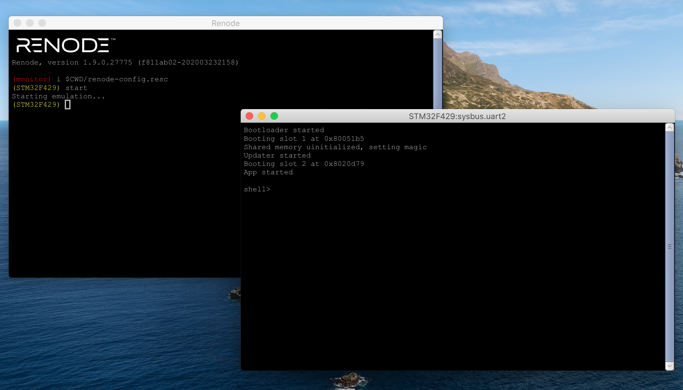
All the code in this post was written for the STM32F429 MCU by ST Micro. While the examples run fine on the STM32F429i discovery board they were developed in Renode, a popular MCU emulation platform.
You can find the complete code example for this blog post in the Interrupt Github repository
Renode
Since writing about Renode for Interrupt, I’ve been looking for an opportunity to use it for another project. This blog post was the perfect pretext. If you are not familiar with Renode, I recommend reading my previous blog post on the topic.
Because we use true firmware images .bin’s rather than elf files in this post, I had to make two
change to the Renode configuration:
- I used
sysbus LoadBinary $bin 0x8000000rather thanLoadELFto load the firmware. - I manually set the Vector Table Offset with
sysbus.cpu VectorTableOffset
0x8000000
. By default, Renode looks for the vector table at0x0which different from the default behavior of the STM32.
Update: As of July 2020, Renode has merged our updates to implement the AICR register so you can run our code on a standard Renode built
Additionally, I had to modify Renode slightly to enable software-controlled
resets. Cortex-M microcontrollers can be reset by writing to the AICR register,
which was not fully implemented in the emulator. As of this writing, this change
is still in review and not yet merged into the emulator. You can find the pull
request on
Github.
Thankfully, building our own version of Renode is relatively
straightforward using their
instructions.
I updated my start.sh script to run my home-built Renode instance rather than
the installed binary:
#!/bin/sh

RENODE_EXE_PATH=~/code/renode/output/bin/Release/Renode.exe

mono64 $RENODE_EXE_PATH renode-config.resc
You will have to update this script to point at your own Renode.exe.
Toolchain
I used the following tools to build my firmware:
- GNU Make 4.2.1 as the build system
-
arm-none-eabi-gccversion 9.2.1 20191025 (release) as compiler
Rather than the STM32Cube HAL, I used an open source MCU HAL called libopencm3
with excellent support for the STM32. I find it easier to use, and like that it
is open source and on Github. The included Makefile will clone libopencm3
during your first build.
Building & Running the Example
The example can be built with Make. From the examples/fwup-architecture
directory:
$ make
  LD            build/fwup-example-boot.elf
  OBJCOPY       build/fwup-example-boot.bin
  LD            build/fwup-example-app.elf
  OBJCOPY       build/fwup-example-app.bin
  XXD           build/app_bin.c
  LD            build/fwup-example-loader.elf
  OBJCOPY       build/fwup-example-loader.bin
  CAT           build/fwup-example.bin
After which you can call ./start.sh to start Renode. You will need to type the
start command in the Renode window to get the emulation going.
High-Level Architecture
Over the years, I’ve come up with a set of basic requirements most DFU systems should fulfill. Let’s walk through these one by one and iteratively design our system.
We start with the simplest possible description of what we want to achieve with DFU: an application that updates itself.
This is not a practical design. For one, self-modifying code is easy to mess up. Let’s see how we might modify this architecture to get to something we’re happy with.
DFU should be separate from the application
The only time I ever broke DFU on a device, I did it without changing a line of
code related to DFU. Unbeknownst to me, our DFU processes accidentally depended on an
uninitialized variable which up until then had always ended up being 0.
Inevitably a new version reshuffled the content of the stack, and all of a
sudden our uninitialized variable held a “1”. This prevented DFU from taking
place.1
The moral to this story: keep your DFU process and your application code separate. Firmware update code is critical and should not be changed unless absolutely necessary. Separating application code from firmware update code allows us to update our application code without risking problems with DFU.
How do we modify our architecture to meet this requirement? We simply split the firmware into a “Loader” and an “Application”. The loader verifies the application, runs it, and can update it.
DFU code should be updatable
While we want to update our DFU code as little as possible, updating it should still be possible. Inevitably we will find a bug in our firmware update code which we must fix. We may want to change our memory map to allocate more code space to our app, or to rotate a security key baked into our Loader.
But where should the code that updates our Loader live? It cannot be in the application, or else we would violate the previous principle. It cannot be in the Loader itself either. That leaves one option: a third program tasked with updating the loader. We’ll call it the “Updater”.
The Updater is loaded by the Loader, perhaps when a specific input is received. All it knows how to do is update the Loader.
DFU should use minimal code space
Every firmware project I’ve ever worked on has run out of code space. At Pebble, we spent months porting our 3.0 firmware to the original watch; most of that time was spent slimming down the code so it could fit within the 512KB of Flash available on that device2.
With that in mind, we should make sure our Loader and Updater do not take more code space than absolutely necessary. Are there ways we can update our design to use less code space? Absolutely!
The key insight here is that the Updater needs to run very rarely and that it never needs to coexist with the application. We can, therefore, use the same “slot” in flash for both the Updater and the Application. The main tradeoff here is that our Loader update flow becomes more complicated as we need to do a DFU to get the Updater, then another to update the loader, then a third to load the application back. In other words:
Go to Loader → DFU Updater in the Application’s place → Load Updater → DFU the new Loader → Reboot into Loader → DFU the Application back in its slot
We can tolerate this complexity because it should not be used often.
DFU failures should not brick the device
This one should be obvious. Whether there is a bug in our DFU process, or a power loss event while we are writing firmware, the device should be able to recover. It may operate in a degraded mode for a bit, but it should at least be able to update itself back to a good state.
Our design already does a reasonable job of this: if we lose power in the middle of an Application update, we can reboot into our Loader and start our update again. There are however two failure modes we must deal with.
First, in the event we lose power while updating the Loader, we could find
ourselves with no valid image at the address the chip boots from (0x0 by
default for Cortex-M, but aliased to 0x80000000 on STM32). The solution is to
add a small, immutable bootloader whose sole job is to sit at the start address
and load our Loader.
Second, what happens if we find ourselves without a functional Loader? We would want to fall back to the Updater. Here again, the small bootloader is the solution. In the event no valid Loader is found, it should try to load whatever is found in the “Application” slot.
In summary, we end up with four programs:
- An immutable Bootloader whose sole job is to load the Loader, and fallback to another image if the Loader is invalid.
- A Loader that can verify our Application image, load it, and update it.
- An Application which does not do any updates itself
- An Updater that temporarily replaces the Application and can update the Loader.
This is not the only valid firmware update architecture, but it avoids many of the pitfalls of DFU without consuming too much code space.
Design Patterns & Recipes
I have put together a full implementation of the Bootloader, the Loader, and the Application in the Interrupt Github repository. While discussing every line in detail is outside of the scope of this conversation, I want to highlight a few patterns I have learned over the years. These include ways to package firmware images, write them to flash, share data between programs, and more!
This post builds upon many ideas previously written about on Interrupt. If you haven’t read them already, I recommend the following:
- How to Write a Bootloader from Scratch
- How to Write Linker Scripts for Firmware
- GNU Build IDs for Firmware
- Building a Tiny CLI Shell for Tiny Firmware
Image Metadata
Firmware images typically need to be bundled alongside some metadata. It identifies what type of image it is, how large it is, what version it is, … etc.
That metadata must be:
- Easy to find and parse for an external program
- Accessible from within the firmware itself
My favorite approach is to add a struct at the beginning of the image to serve as a header. Here’s what it looks like:
// image.h
typedef struct __attribute__((packed)) {
    uint16_t image_magic;
    uint16_t image_hdr_version;
    uint32_t crc;
    uint32_t data_size;
    uint8_t image_type;
    uint8_t version_major;
    uint8_t version_minor;
    uint8_t version_patch;
    uint32_t vector_addr;
    uint32_t reserved;
    char git_sha[8];
} image_hdr_t;
The contents of that header will vary per application, but you must include:
- A way to indicate that the header is valid (here we used a constant in
image_magic) - A version for the header, and
- The address of the start of your vector table.
Note: A “magic” value is typically a constant which is used to identify a file format or data structure. In this case, every image should have the 0xcafe bytes in its first two bytes. If the bytes are not there, the image is not valid!
Each of our images must fill in its own header. For example, here it is for my Application:
// app.c
image_hdr_t image_hdr __attribute__((section(".image_hdr"))) = {
    .image_magic = IMAGE_MAGIC,
    .image_hdr_version = IMAGE_VERSION_CURRENT,
    .image_type = IMAGE_TYPE_APP,
    .version_major = 1,
    .version_minor = 0,
    .version_patch = 1,
    .vector_addr = (uint32_t)&vector_table,
    // GIT_SHA is generated by Makefile
    .git_sha = GIT_SHA,
    // populated as part of a post compilation step
    .crc = 0,
    .data_size = 0,
};
You will notice the section attribute, which is used to place the variable in
a specific section of our firmware. This is paired with some code in our linker
script which declares that sections and puts it at the very start of flash:
// app.ld
SECTIONS
{
    .image_hdr : {
        KEEP (*(.image_hdr))
    } > slot2rom

    /* Vector table must be 128-bit aligned */
    . = ALIGN(128);

    .text : {
        *(.vectors)    /* Vector table */
        *(.text*)    /* Program code */
        . = ALIGN(4);
        *(.rodata*)    /* Read-only data */
        . = ALIGN(4);
    } >slot2rom

    ...
};
Some data can simply be hardcoded into the header. In my case, this includes the
image_magic, the semantic version, the image type, the header version, and the
vector table address. Other bits must be read from the environment and injected
as DEFINES by our Makefile. For example, this is how we get the GIT_SHA:
# Makefile
GIT_SHA := \"$(shell $(GIT) rev-parse --short HEAD)\"
DEFINES += GIT_SHA=$(GIT_SHA)
CFLAGS += $(foreach d,$(DEFINES),-D$(d))
The GIT_SHA macro can then be called in our code to get the short (7-char)
hash as a string.
Some header information can only be calculated after the firmware has been compiled and linked. For example, the length of the binary, its CRC, or its cryptographic signature. To add it to the header, we must edit the binary directly.
This is best done with a simple Python script. Chris whipped one up for my example which you can find alongside the code. The code calculates the size and CRC for the binary and adds those values to the header.
Our Makefile rules to generate our images end up looking like this:
$(BUILD_DIR)/$(PROJECT)-%.bin: $(BUILD_DIR)/$(PROJECT)-%.elf
	arm-none-eabi-objcopy $^ $@ -O binary
	python patch_image_header.py $@
That’s it! We can now display the information in our firmware:
// app.c
printf("App STARTED - version %d.%d.%d (%s) - CRC 0x%lx\n",
       image_hdr.version_major,
       image_hdr.version_minor,
       image_hdr.version_patch,
       image_hdr.git_sha,
       image_hdr.crc);
And as expected we get:
App STARTED - version 1.0.1 (e8e8d53) - CRC 0xeb4f7f52
Loading Images
Both the Bootloader and the Loader need to load firmware images and start them. This includes:
- Locating them
- Verifying them, and
- Starting them.
The code may look something like this:
// boot.c
for (image_slot_t slot = IMAGE_SLOT_1; slot < IMAGE_NUM_SLOTS; ++slot) {
    const image_hdr_t *hdr = image_get_header(slot);
    if (hdr == NULL) {
        continue;
    }
    if (image_validate(slot, hdr) != 0) {
        continue;
    }

    printf("Booting slot %d\n", slot);
    image_start(hdr);
}

// No image found, go into DFU mode
Here our approach to locating images is simple: we use hardcoded “slots” where
we expect images. Slot 1 is at 0x8004000, and slot 2 is at 0x8020000. We
simply iterate through the slots looking for valid headers.
Remember that the first field of our image header is the “magic” value. In
image_get_header we read the header and verify the magic value.
// image.c
const image_hdr_t *image_get_header(image_slot_t slot) {
    const image_hdr_t *hdr = NULL;

    switch (slot) {
        case IMAGE_SLOT_1:
            hdr = (const image_hdr_t *)&__slot1rom_start__;
            break;
        case IMAGE_SLOT_2:
            hdr = (const image_hdr_t *)&__slot2rom_start__;
            break;
        default:
            break;
    }

    if (hdr && hdr->image_magic == IMAGE_MAGIC) {
        return hdr;
    } else {
        return NULL;
    }
}
To validate the image, we compute its CRC and compare it with the value written in the header. This will allow you to catch data corruption or bit errors, and save you some trouble down the line. Note that verifying CRC on boot is not appropriate for every application, as it can slow down boot significantly.
int image_validate(image_slot_t slot, const image_hdr_t *hdr) {
    void *addr = (slot == IMAGE_SLOT_1 ? &__slot1rom_start__ : &__slot2rom_start__);
    addr += sizeof(image_hdr_t);
    uint32_t len = hdr->data_size;
    uint32_t a = crc32(addr, len);
    uint32_t b = hdr->crc;
    if (a == b) {
        return 0;
    } else {
        printf("CRC Mismatch: %lx vs %lx\n", a, b);
        return -1;
    }
}
Last but not least we start the image by extracting the vector table address
from the header, writing it to the VTOR register (which tells the chip that
the vector table address has moved), and branching to it with a bit of assembly.
static void prv_start_image(void *pc, void *sp) {
    __asm("           \n\
          msr msp, r1 \n\
          bx r0       \n\
    ");
}

void image_start(const image_hdr_t *hdr) {
    const vector_table_t *vectors = (const vector_table_t *)hdr->vector_addr;
    SCB_VTOR = (uint32_t)vectors;
    prv_start_image(vectors->reset, vectors->initial_sp_value);
     __builtin_unreachable();
}
If no image is found, the loader should go into DFU mode and waits for a new image to be transferred.
Note: The
VTORregister is available on the Cortex-M0+,M3,M4,M7, but not on the older M0. Unfortunately, this makes building a bootloader much more complicated on that platform.
Writing & Committing Images
Writing a new firmware image is the whole purpose of this exercise, so how do we do the deed? We won’t cover transferring the image over to your firmware, that varies greatly depending on your use, but once the transfer has occurred we must:
- Write the image
- Verify it, and
- Mark it as valid.
At the high level, here’s our flow:
int perform_update(void *fw_payload, size_t fw_payload_len) {
    uint8_t *data_ptr = fw_payload;
    image_hdr_t *hdr = (image_hdr_t *)data_ptr;
    data_ptr += sizeof(image_hdr_t);

    if (dfu_write_data(IMAGE_SLOT_2,
                data_ptr,
                fw_payload_len)) {
        return -1;
    }

    if (image_validate(IMAGE_SLOT_2, hdr)) {
        return -1;
    };

    if (dfu_commit_image(IMAGE_SLOT_2, hdr)) {
        return -1;
    };

    scb_reset_system();
    __builtin_unreachable();
}
Writing the data is relatively straightforward. For flash memory, you’ll
typically erase the relevant sector, then use the page_program function
provided with your flash driver to write new data. Make sure however that you do
not write the image header during this process. The header will only be written
during the “commit” phase.
We’ve covered how to verify an image in the previous section. Here again, we may check the CRC, or verify a cryptographic signature.
If at any point the update is interrupted, the header will be missing and our Loader will refuse to load the image. Once everything checks out, we commit the image by writing the header. This marks the image as valid and allows it to be loaded.
Here is my implementation of the commit step, it’s nothing too complicated:
int dfu_commit_image(image_slot_t slot, const image_hdr_t *hdr) {
    uint32_t addr = (uint32_t)(slot == IMAGE_SLOT_1 ?
                               &__slot1rom_start__ : &__slot2rom_start__);

    uint8_t *data_ptr = (uint8_t *)hdr;
    for (int i = 0; i < sizeof(image_hdr_t); ++i) {
        flash_program_byte(addr + i, data_ptr[i]);
    }

    return 0;
}
Just as writing the header marks an image as valid, we can invalidate an image simply by zeroing it out. This is much faster than erasing the whole flash, and won’t leave us in a half-working state (e.g. having erased only half of the image).
int dfu_invalidate_image(image_slot_t slot) {
    // We just write 0s over the image header
    uint32_t addr = (uint32_t)(slot == IMAGE_SLOT_1 ?
                               &__slot1rom_start__ : &__slot2rom_start__);
    for (int i = 0; i < sizeof(image_hdr_t); ++i) {
        flash_program_byte(addr + i, 0);
    }

    return 0;
}
Shared Memory
It is often useful to exchange information between our different programs. The application may want to signal to the loader that it should go into DFU mode on the next reboot, and the loader may want to pass arguments to the application.
On some platforms, scratch registers can be used as mailboxes between the different programs. This is the case for the STM32. For all others, we must make do with RAM. “But François, isn’t RAM volatile”? Not quite: as long as your MCU remains powered, the SRAM will hold its state. For short durations, you can treat it as non-volatile storage.
The simplest way to carve out an area of RAM to be shared across our programs is to declare it in a shared linker script. We’ve covered linker scripts on Interrupt, so I won’t detail the syntax again. This is what it looks like:
// memory_map.ld
MEMORY
{
  sharedram (rwx): ORIGIN = 0x20000000, LENGTH = 256
  ram (rwx)      : ORIGIN = 0x20000100, LENGTH = 128K - LENGTH(sharedram)
}

SECTIONS
{
    .shared_memory (NOLOAD) : {
        KEEP(*(.shared_memory))
    } >sharedram
}
This shared linker script can then be included by the individual program’s
linker script with the INCLUDE directive.
Now that we have a region of RAM defined, we can define a structure for it. You
will want that structure to be packed to guard against alignment mismatches
across your programs as you update compiler flags and versions. Here again, we
use the section attribute to assign our symbol to the .shared_memory section.
// shared_memory.c
typedef struct __attribute__((packed)) {
    uint32_t magic;
    uint32_t flags;
} shared_memory_t;

volatile shared_memory_t shared_memory __attribute__((section(".shared_memory")));
In the event of power loss, RAM will be left in an indeterminate state. We’ll need to detect this and reset the shared memory when it happens. On the STM32, the RCC peripheral can tell us whether or not we lost power. When power is lost, we’ll erase the magic value at the beginning of our struct so that the rest of our code knows not to trust the shared memory region. Stick the following code somewhere in your early init sequence.
(thank you to interrupt reader dreiss for sending us this code snippet)
if (RCC->CSR & RCC_CSR_PORRSTF) {
    // Power loss has occurred.
    // Clear magic to ensure we initialize shared_memory.
    shared_memory.magic = 0;
    __DMB();  // Possibly not necessary.
    // Clear reset flags.
    RCC->CSR |= RCC_CSR_RMVF;
}
When we inspect our shared memory further down the line, we check the magic number and initialize the struct if it isn’t what we expect.
void shared_memory_init(void) {
    if (shared_memory.magic != MAGIC) {
        printf("Shared memory uinitialized, setting magic\n");
        memset(&shared_memory, 0, sizeof(shared_memory_t));
        shared_memory.magic = MAGIC;
    }
}
A common use case for shared memory is to signal to the Loader that we should not load the Application on the next boot and instead go into DFU mode. We use a simple flag to signal this:
bool shared_memory_is_dfu_requested(void) {
    return (shared_memory.flags & DFU_REQUESTED) != 0;
}

void shared_memory_set_dfu_requested(bool yes) {
    shared_memory.flags |= DFU_REQUESTED;
}
Using the shell from Tyler’s last post on CLI’s, I created a shell command in the Application to set that flag and reboot:
int cli_command_dfu_mode(int argc, char *argv[]) {
    shell_put_line("Rebooting into DFU mode");
    shared_memory_set_dfu_requested(true);
    scb_reset_system();
    while (1) {}
    return 0;
}
In the Loader, we systematically check the DFU flag before we start the Application.
// loader.c
if (!shared_memory_is_dfu_requested()) {
    // start app
}

printf("Entering DFU Mode\n");
shared_memory_set_dfu_requested(false);
Boot Stability
An especially terrible way to brick a device is to go into a boot loop. It goes like this: a new update has a deadly bug, and crashes shortly upon boot. Your device then enters a loop. It starts, goes into the loader, then the application, then crashes. Again, and again, and again.
To avoid boot-looping, I recommend using a boot counter which gets incremented on every boot and cleared once the application is deemed “stable”. Once the counter reaches a certain threshold, the Loader stops loading the Application and instead goes into DFU mode.
How might we implement this? With our shared memory region! Let’s add a boot counter to it, and implement some getters/setters:
// shared_memory.c
typedef struct __attribute__((packed)) {
    uint32_t magic;
    uint32_t flags;
    uint8_t boot_counter;
} shared_memory_t;

void shared_memory_increment_boot_counter(void) {
    shared_memory.boot_counter++;
}

void shared_memory_clear_boot_counter(void) {
    shared_memory.boot_counter = 0;
}

uint8_t shared_memory_get_boot_counter(void) {
    return shared_memory.boot_counter;
}
Before it starts the app, the Loader checks the counter and skips loading the app if the counter exceeds a threshold:
const int max_boot_attempts = 3;
if (shared_memory_get_boot_counter() >= max_boot_attempts) {
    shared_memory_clear_boot_counter();
    printf("App unstable, dropping back into DFU mode\n");
    break;
}
Otherwise, it increments the counter and starts the application.
printf("Booting slot 2\n");
shared_memory_increment_boot_counter();
image_start(hdr);
Last but not least, the Application must clear the counter once it believes it is stable. When might that be? That depends on your application. One option is to set a timer and mark the app as stable after it has been running for a few minutes. Another option is to wait until it has managed to connect to a gateway or the cloud. Whatever you do, the main requirement is that the Application can receive an instruction to boot into DFU mode, so that we can bail out if it turns out there is another bug lurking.
In my example, I simply created a firmware shell command which marks the app as stable:
int cli_command_mark_stable(int argc, char *argv[]) {
    shell_put_line("Marking app as stable");
    shared_memory_clear_boot_counter();
    return 0;
}
Closing
I hope this post will prove useful next time you need to implement DFU on a device! While there are plenty of good reasons to stray from this design, it is a solid base upon which to build.
In systems where code space isn’t a challenge, I would have made different choices. For example, I would have allocated a slot to the Updater. I would also recommend allocating two slots to the Application so A/B updates can be implemented.
One topic we did not cover at all is security. In 2020, firmware security is an important topic and DFU is a key component in the security architecture of a device. We will cover this in a post next month.
As always, we’d love to hear from you. Do you have design rules of thumb for firmware update that we did not cover? Let us know! And if you see anything you’d like to change, don’t hesitate to submit a pull request or open an issue on Github
Interested in learning more device firmware update best practices? Watch this webinar recording
References
-
This is not the end to this story. My cofounder Chris eventually found a set of inputs to provide to the device which would set the stack just so and allow us to update out of that state. Phew! ↩
-
At the time, we wrote a blog post about it. You can still read it on the Internet Archive ↩
 François Baldassari has worked on the embedded software teams at Sun, Pebble, and Oculus. He is currently the CEO of Memfault.