Cortex-M MCU Emulation with Renode
In this new era of work-from-home, firmware engineers may not have all the equipment and development boards they are used to having at the office. One way around this? Emulation!
While they’re not quite the real thing, emulators can run our firmware, print data over UART, read registers from I2C sensors, and even run a filesystem on a SPI flash device. That’s more than enough to write some real firmware!
In this post, I walk through setting up the Renode emulator and running a firmware in it for STM32. Using that setup, we’ll debug our firmware, run it through integrated tests, and shorten the iteration cycle of development.
Table of Contents
What is Renode?
Renode is an open-source Emulator for embedded platforms. Today, it supports x86 (Intel Quark), Cortex-A (NVIDIA Tegra), Cortex-M, SPARC (Leon), and RISC-V based platforms.
Renode can take the same firmware you are running in production, and run it against emulated cores, peripherals, and even sensors and actuators. Better yet, its extensive networking support and multi-system emulation make it a shoe in for testing systems made up of multiple devices talking together.
With Renode, you can start development before your hardware is ready, test your firmware without deploying racks of hardware, and shorten your iteration cycles by cutting out flash loading delays.
Renode is built using the Mono framework, which allows it to run cross-platform.
Why not QEMU? - Readers who have experience with emulation will point out that QEMU has existed for a long time, and is capable of emulating Cortex-M targets. In our experience, QEMU is focused on emulating systems meant for higher-level OSes (e.g. Linux computers) rather than embedded devices. To date, it only supports two cortex-M series targets, both made by TI.
Installing Renode
The Renode project releases installers for Windows, MacOS, and multiple Linux distributions. As of this writing, you can find the v1.9 release on Github.
This guide was written on MacOS, though it is not OS specific.
To verify your Renode installation, you can run one of the examples:
- Open Renode, on MacOS I prefer to use the command line directly with
$ sh /Applications/Renode.app/Contents/MacOS/macos_run.command - A Renode terminal window will open. Load the example with
start @scripts/single-node/stm32f4_discovery.resc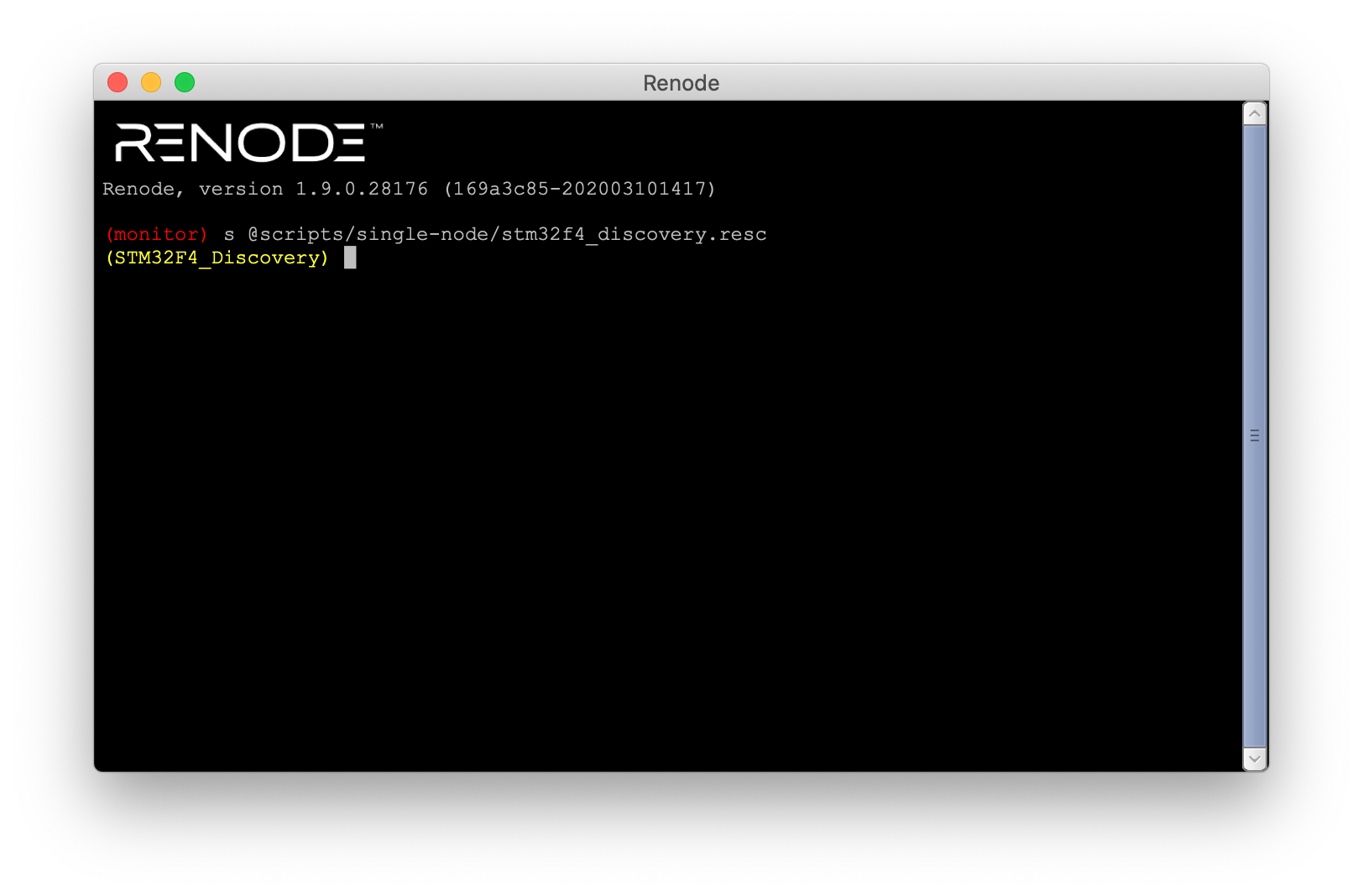
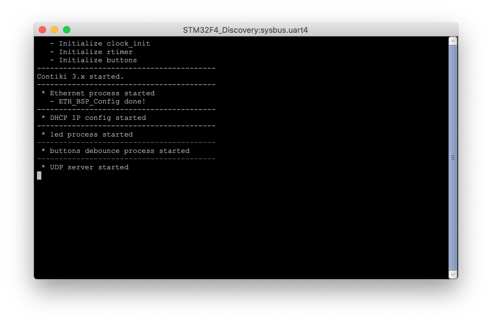
- A second terminal window should open, displaying serial output
Running our firmware in Renode
Let’s write a hello world firmware to run via Renode. We will target the STM23F4 Discovery board, as the emulator supports it out of the box.
A simple firmware
I chose to use libopencm31, an open-source library for ARM cortex-M microcontrollers. I enjoy how easy it is to get started with it and appreciate the consistent API across microcontrollers. Note however that the library is still in its early stages and likely not fit for production use. I used the libopencm3 template 2 as a starting point.
To get to a “hello, world!”, we must:
- Setup the peripheral clocks
- Enable the UART GPIOs
- Configure the UART peripheral
- Implement the
_writesyscall
I’ve reproduced the source code below, you can find the full project (Makefile included) in the interrupt Github repo.
#include <errno.h>
#include <stdio.h>
#include <unistd.h>
#include <libopencm3/stm32/rcc.h>
#include <libopencm3/stm32/gpio.h>
#include <libopencm3/stm32/usart.h>

static void clock_setup(void)
{
    /* Enable GPIOD clock for LED & USARTs. */
    rcc_periph_clock_enable(RCC_GPIOD);
    rcc_periph_clock_enable(RCC_GPIOA);

    /* Enable clocks for USART2. */
    rcc_periph_clock_enable(RCC_USART2);
}

static void usart_setup(void)
{
    /* Setup USART2 parameters. */
    usart_set_baudrate(USART2, 115200);
    usart_set_databits(USART2, 8);
    usart_set_stopbits(USART2, USART_STOPBITS_1);
    usart_set_mode(USART2, USART_MODE_TX);
    usart_set_parity(USART2, USART_PARITY_NONE);
    usart_set_flow_control(USART2, USART_FLOWCONTROL_NONE);

    /* Finally enable the USART. */
    usart_enable(USART2);
}

static void gpio_setup(void)
{
    /* Setup GPIO pin GPIO12 on GPIO port D for LED. */
    gpio_mode_setup(GPIOD, GPIO_MODE_OUTPUT, GPIO_PUPD_NONE, GPIO12);

    /* Setup GPIO pins for USART2 transmit. */
    gpio_mode_setup(GPIOA, GPIO_MODE_AF, GPIO_PUPD_NONE, GPIO2);

    /* Setup USART2 TX pin as alternate function. */
    gpio_set_af(GPIOA, GPIO_AF7, GPIO2);
}

int _write(int file, char *ptr, int len)
{
    int i;

    if (file == STDOUT_FILENO || file == STDERR_FILENO) {
        for (i = 0; i < len; i++) {
            if (ptr[i] == '\n') {
                usart_send_blocking(USART2, '\r');
            }
            usart_send_blocking(USART2, ptr[i]);
        }
        return i;
    }
    errno = EIO;
    return -1;
}

int main(void) {
    clock_setup();
    gpio_setup();
    usart_setup();

    printf("hello world!\n");

    while (1) {}

    return 0;
}
If all goes well, we now have a renode-example.elf file we can load in the
emulator.
Running our firmware in Renode
Next up, we must spin up a machine in Renode and run our firmware in it.
Like we did earlier, we first start Renode:
$ git clone https://github.com/memfault/interrupt.git
$ cd example/renode/
$ make
# Note: on Linux this just is the "renode" command
$ sh /Applications/Renode.app/Contents/MacOS/macos_run.command
The window that pops up is called the Renode monitor. In it, you can run Renode commands.
We now need to create a machine. A machine represents a device, which can have a number of cores. Renode can run multiple machines in a single run.
We can create, add, and remove machines with the mach command:
(monitor) mach create
(machine-0)
The prompt now includes our machine name. Since we did not name our machine, it just says “machine-0”.
Next, we configure our machine. We could specify each bus and peripheral by hand, but instead we will load a prebuilt configuration.
(machine-0) machine LoadPlatformDescription @platforms/boards/stm32f4_discovery-kit.repl
(machine-0)
You will notice that the path is prepended with the @ sign. This is a C#-ism.
Renode will load absolute paths, as well as paths relative to your working
directory, and paths relative to the renode installation. In our case, we used
the latter as platforms is bundled with the Renode installation.
Next, we load our firmware:
(machine-0) sysbus LoadELF @renode-example.elf
(machine-0)
Note: You can also load
.binfiles withsysbus LoadBinary
Before we start the machine, we want to do one last thing: open a terminal to display UART data. Some peripherals come with what Renode calls “Analyzers”, which are ways to display their state and data. We enabled UART2 in our firmware, so we will show the analyzer for UART2.
(machine-0) showAnalyzer sysbus.uart2
(machine-0)
You should now have two Renode windows open, the monitor window and the UART2 window.
We are now ready to run our simulation with the start command:
(machine-0) start
Adding CCM memory
… Well, this is embarrassing. Nothing happened.
In the terminal window we used to start the Renode app, we see line after line of warnings:
[...]
20:46:07.5783 [WARNING] sysbus: [cpu: 0x8000926] WriteByte to non existing peripheral at 0x10152AA3, value 0x0.
20:46:07.5783 [WARNING] sysbus: [cpu: 0x8000926] WriteByte to non existing peripheral at 0x10152AA4, value 0x0.
20:46:07.5783 [WARNING] sysbus: [cpu: 0x8000926] WriteByte to non existing peripheral at 0x10152AA5, value 0x0.
20:46:07.5795 [WARNING] sysbus: [cpu: 0x8000926] WriteByte to non existing peripheral at 0x10152AA6, value 0x0.
20:46:07.5799 [WARNING] sysbus: [cpu: 0x8000926] WriteByte to non existing peripheral at 0x10152AA7, value 0x0.
20:46:07.5800 [WARNING] sysbus: [cpu: 0x8000926] WriteByte to non existing peripheral at 0x10152AA8, value 0x0.
20:46:07.5800 [WARNING] sysbus: [cpu: 0x8000926] WriteByte to non existing peripheral at 0x10152AA9, value 0x0.
20:46:07.5800 [WARNING] sysbus: [cpu: 0x8000926] WriteByte to non existing peripheral at 0x10152AAA, value 0x0.
20:46:07.5801 [WARNING] sysbus: [cpu: 0x8000926] WriteByte to non existing peripheral at 0x10152AAB, value 0x0.
20:46:07.5801 [WARNING] sysbus: [cpu: 0x8000926] WriteByte to non existing peripheral at 0x10152AAC, value 0x0.
20:46:07.5801 [WARNING] sysbus: [cpu: 0x8000926] WriteByte to non existing peripheral at 0x10152AAD, value 0x0.
20:46:07.5802 [WARNING] sysbus: [cpu: 0x8000926] WriteByte to non existing peripheral at 0x10152AAE, value 0x0.
20:46:07.5802 [WARNING] sysbus: [cpu: 0x8000926] WriteByte to non existing peripheral at 0x10152AAF, value 0x0.
[...]
Let’s quit the emulator for now and restart it once things are fixed
(monitor) quit
Looking at our chip’s memory map, we notice that 0x10XXXXXX is in the CCM
region. Turns out the renode model does not implement it. Fear not! This is
easily fixed.
The easiest way to modify our Machine to add the CCM RAM is to write a Renode Platform (or “repl”) file. Repl files use YAML-like syntax to define peripherals, including their type, address, and size.
You can read more about the Platform Description file format in the Renode Documentation Adding our CCM region requires the following:
// In "add-ccm.repl"
ccm: Memory.MappedMemory @ sysbus 0x10000000
    size: 0x10000
Since platform descriptions are composable, We can now load that file using the
same LoadPlatformDescription command we used earlier:
(machine-0) machine LoadPlatformDescription @add-ccm.repl
(machine-0)
Putting it all together we have:
(monitor) mach create
(machine-0) machine LoadPlatformDescription @platforms/boards/stm32f4_discovery-kit.repl
(machine-0) sysbus LoadELF @renode-example.elf
(machine-0) machine LoadPlatformDescription @add-ccm.repl
(machine-0) showAnalyzer sysbus.uart2
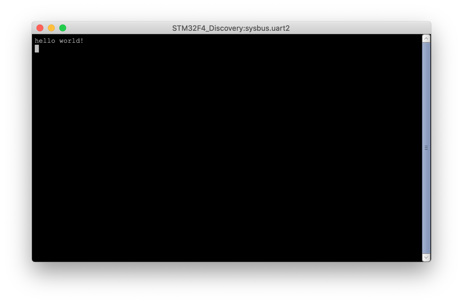
(machine-0) start
And voila, we now have hello world! string in the analyzer!
Automating setup with a .resc script
Typing all this out is a bit of a hassle, this is where Renode Scripts “.resc” files come in.
Not much documentation can be found on .resc files, but here are a few things
I was able to figure out:
- variables can be created with
$and assigned with=. For example:$hello = "world". - renode are executed in the order written
- macros can be defined with the keyword
macro, and start and end with"""
Putting this all together, we can write the following script to setup our hello world example:
# Filename: renode-config.resc
$bin?=@renode-example.elf

# Create Machine & Load config
mach create
machine LoadPlatformDescription @platforms/boards/stm32f4_discovery-kit.repl
machine LoadPlatformDescription @add-ccm.repl

# Create a terminal window showing the output of UART2
showAnalyzer sysbus.uart2

macro reset
"""
    sysbus LoadELF $bin
"""

runMacro $reset
We can start renode with this script by passing it as an argument to our renode
command. I wrapped it all in a start.sh shell script:
#!/bin/sh

sh /Applications/Renode.app/Contents/MacOS/macos_run.command renode-config.resc
Reset macro: Renode looks for a macro named “reset”, and uses it to reset the machine when the
machine Resetormachine RequestResetare issued. In our script, we use that macro to reload our elf file every time, so we do not have to do it manually between resets. This also guarantees that the latest elf file is picked up and allows us to iterate on code quickly.
Managing machine lifecycle
Starting renode every time you want to restart your machine is cumbersome. Instead, we can use lifecycle commands to start, pause, and reset our machine:
# start a machine
(machine-0) start
# pause a machine
(machine-0) pause
# reset a machine
(machine-0) machine RequestReset
These are all pretty self-explanatory. Note that the RequestReset command will
invoke your reset macro if you have one specified.
Last but not least, you can drop the whole emulation by using the Clear
command.
Debugging with Renode
Inevitably things will go wrong and you will need to debug them. This is one area where Renode really shines.
Tracing Function Calls
One of the advantages of emulators is that they make it much easier to introspect and trace the device state. One of the more useful hooks exposed by Renode is execution tracing. Provided you fed the emulator an ELF file with debug symbols, Renode will print out log out every function being executed.
Going back to our hello world example, we can enable function tracing with a single command:
(machine-0) sysbus.cpu LogFunctionNames True
(machine-0)
You will likely want to write the output to a file rather than stdout, you can do this with a single command as well:
(machine-0) logFile @/tmp/function-trace.log
(machine-0)
Once we’ve started our emulation, we can retrieve the file and inspect it:
[...]
23:12:16 [INFO] cpu: Entering function _write at 0x80001D8¬
23:12:16 [INFO] cpu: Entering function usart_send_blocking (entry) at 0x80003B4¬
23:12:16 [INFO] cpu: Entering function usart_wait_send_ready (entry) at 0x80003D2¬
23:12:16 [INFO] cpu: Entering function usart_wait_send_ready at 0x80003D8¬
23:12:16 [INFO] cpu: Entering function usart_send_blocking at 0x80003BE¬
23:12:16 [INFO] cpu: Entering function usart_send (entry) at 0x80003CA¬
23:12:16 [INFO] cpu: Entering function _write at 0x80001E2¬
23:12:16 [INFO] cpu: Entering function _write at 0x80001BE¬
23:12:16 [INFO] cpu: Entering function _write at 0x80001CA¬
23:12:16 [INFO] cpu: Entering function _write at 0x80001D0¬
23:12:16 [INFO] cpu: Entering function usart_send_blocking (entry) at 0x80003B4¬
23:12:16 [INFO] cpu: Entering function usart_wait_send_ready (entry) at 0x80003D2¬
23:12:16 [INFO] cpu: Entering function usart_wait_send_ready at 0x80003D8¬
23:12:16 [INFO] cpu: Entering function usart_send_blocking at 0x80003BE¬
23:12:16 [INFO] cpu: Entering function usart_send (entry) at 0x80003CA¬
23:12:16 [INFO] cpu: Entering function _write at 0x80001D8¬
23:12:16 [INFO] cpu: Entering function usart_send_blocking (entry) at 0x80003B4¬
[...]
GDB Integration
When it comes to debugging, GDB is my go to tool. I was pleasantly surprised to learn that Renode will spin up a GDB server for you out of the box. This is extremely easy to use.
First, we enable the GDB server and bind it to port 3333:
(machine-0) machine StartGdbServer 3333
(machine-0)
Note: For the example config we have added this to renode-config.resc so it happens automatically when spinning up the environment
In a separate terminal window, we start GDB and connect to the server on port 3333.
$ arm-none-eabi-gdb renode-example.elf
GNU gdb (GNU Tools for Arm Embedded Processors 8-2018-q4-major)
8.2.50.20181213-git
Copyright (C) 2018 Free Software Foundation, Inc.
License GPLv3+: GNU GPL version 3 or later <http://gnu.org/licenses/gpl.html>
This is free software: you are free to change and redistribute it.
There is NO WARRANTY, to the extent permitted by law.
Type "show copying" and "show warranty" for details.
This GDB was configured as "--host=x86_64-apple-darwin10
--target=arm-none-eabi".
Type "show configuration" for configuration details.
For bug reporting instructions, please see:
<http://www.gnu.org/software/gdb/bugs/>.
Find the GDB manual and other documentation resources online at:
    <http://www.gnu.org/software/gdb/documentation/>.

For help, type "help".
Type "apropos word" to search for commands related to "word"...
Reading symbols from renode-example.elf...

(gdb) target remote :3333
Remote debugging using :3333
0x00000000 in ?? ()
We can then issue monitor commands to renode via the monitor gdb command, and
debug as we would a real target
(gdb) break main
Breakpoint 1 at 0x80001f8: file renode-example.c, line 62.
(gdb) monitor start
Starting emulation...
(gdb) c
Continuing.

Breakpoint 1, main () at renode-example.c:62
62              clock_setup();
(gdb) step
rcc_periph_clock_enable (clken=clken@entry=RCC_GPIOD) at
../common/rcc_common_all.c:136
136             _RCC_REG(clken) |= _RCC_BIT(clken);
(gdb) n
clock_setup () at renode-example.c:12
12              rcc_periph_clock_enable(RCC_GPIOA);
(gdb) n
15              rcc_periph_clock_enable(RCC_USART2);
(gdb)
Renode & Integration Tests
Another area where emulation really shines is the ability to run automated tests without hardware. Renode integrates with the Robot Framework3 to enable this uses case.
A full tutorial on the Robot Framework is outside of the scope of this post, but it is already quite useful.
To make the test more interesting, let’s add a button to our firmware. The STM32 discovery board we are emulating has one on Port A pin 0, which we can enable with a few lines of code:
static void button_setup(void)
{
    /* Enable GPIOA clock. */
    rcc_periph_clock_enable(RCC_GPIOA);

    /* Set GPIOA0 to 'input floating'. */
    gpio_mode_setup(GPIOA, GPIO_MODE_INPUT, GPIO_PUPD_NONE, GPIO0);
}
We then modify our main function to test the state of the button
    bool button_is_pressed = false;

    while (1) {
        if (!button_is_pressed && gpio_get(GPIOA, GPIO0)) {
            button_is_pressed = true;
        } else if (button_is_pressed && !gpio_get(GPIOA, GPIO0)) {
            printf("button pressed\n");
            button_is_pressed = false;
        }
    }
Not how we’d do it in production, but it works!
We can then write a simple Robot Framework script to exercise our firmware:
# Filename: test-button.robot
*** Settings ***
Suite Setup                   Setup
Suite Teardown                Teardown
Test Setup                    Reset Emulation
Resource                      ${RENODEKEYWORDS}

*** Test Cases ***
Should Handle Button Press
    Execute Command         mach create
    Execute Command         machine LoadPlatformDescription @platforms/boards/stm32f4_discovery-kit.repl
    Execute Command         machine LoadPlatformDescription @${PATH}/add-ccm.repl
    Execute Command         sysbus LoadELF @${PATH}/renode-example.elf

    Create Terminal Tester  sysbus.uart2

    Start Emulation

    Wait For Line On Uart   hello world
    Test If Uart Is Idle    3
    Execute Command         sysbus.gpioPortA.UserButton Press
    Test If Uart Is Idle    3
    Execute Command         sysbus.gpioPortA.UserButton Release
    Wait For Line On Uart   button pressed
This test will wait for the “hello world” string to print, then press and release the button and wait for “button pressed” to print.
To run the test, we need to checkout and build the Renode codebase. You can find
step by step instructions on their website4. We can then use the
run_tests.py script to execute our test.
python -u <path-to-renode>/tests/run_tests.py tests/test-button.robot -r test_results --variable PATH:$PWD
You’ll notice a few things:
- We passed a “test_results” folder to the script, which is a location that HTML test results will be written
- We must pass the path to our working directory in a variable, as it is not propagated automatically
To make life easier, I wrapped this command in a shell script here as well:
#!/bin/sh

RC=${RENODE_CHECKOUT:-~/code/renode}

python -u $RC/tests/run_tests.py tests/test-button.robot -r test_results --variable PATH:$PWD
Running this shell script, we observe the test running!
$ ./test.sh
Preparing suites
Starting suites
Running tests/test-button.robot
+++++ Starting test 'test-button.Should Handle Button Press'
+++++ Finished test 'test-button.Should Handle Button Press' in 8.35 seconds with status OK
Cleaning up suites
Aggregating all robot results
Output: /Users/francois/code/interrupt/example/renode/test_results/robot_output.xml
Log: /Users/francois/code/interrupt/example/renode/test_results/log.html
Report: /Users/francois/code/interrupt/example/renode/test_results/report.html
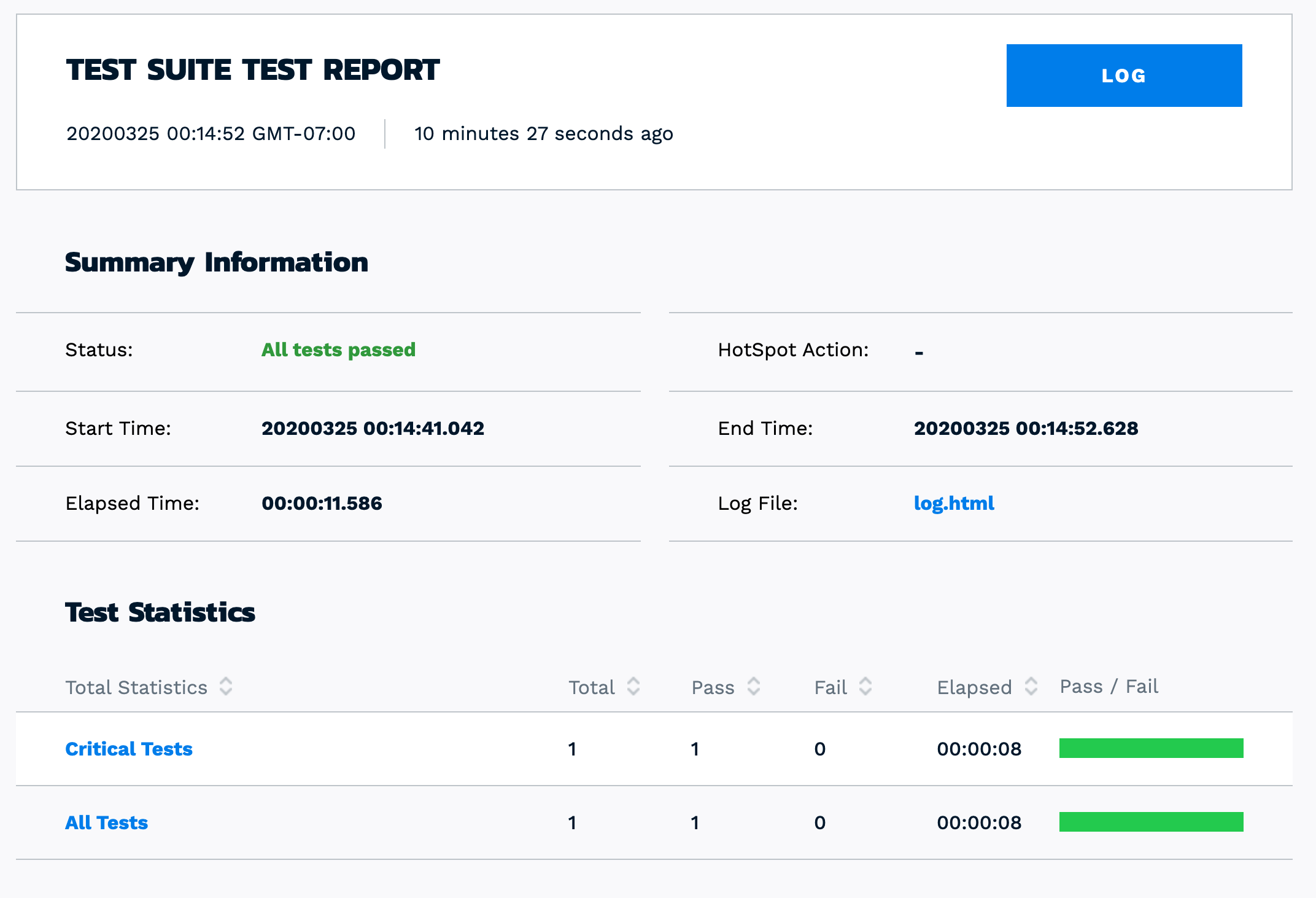
Tests finished successfully :)
Success! As a bonus, the robot framework generates some pretty HTML reports:
Closing
While we only scratched the surface of what Renode is capable of, I hope this post helped you get up and running with firmware emulation.
In a future post, we will show how to model a custom device in Renode with custom Platform Description files and some Python peripheral implementations.
All the code used in this blog post is aavailable on Github.
See anything you'd like to change? Submit a pull request or open an issue on our GitHub
References
 François Baldassari has worked on the embedded software teams at Sun, Pebble, and Oculus. He is currently the CEO of Memfault.