Smart Ring Development (Part 1) - Research and Prototype
This series of articles discusses the development of a SOTA Open Smart Ring - a tiny wearable packed with electronics that fits on your (even the smallest) finger. We dive deep into what it means to develop such a product, its challenges, and ultimately, how to make it a manufacturable and usable piece.
Introduction
In this first article, we’ll look at the first typical stage of new product development for a hardware project - research and prototype. Let’s first start with the idea, though. In early 2020, my friend and I had an idea to build a Smart Ring to control music. Back then, the only known Smart Ring was Oura, and they were at their second generation, still off Kickstarter (after a very successful first generation Kickstarter). It seemed the wearable market was finally booming, and consumers were seeking new electronic gadgets. We thought it would be really cool to build a Smart Ring that acts as a remote control for music, offering typical functions like pause/play, volume up/down, and next/previous track, all in a form that fits on the finger. The use case (not particularly strong in hindsight, but more on that later) was to provide the ability to control music at times when it’s inconvenient to do so, such as when cycling or at the gym (who wants to touch their phone with sweaty hands, right?). Ultimately, the problem we were solving wasn’t substantial enough from a business standpoint, but we had a great deal of fun building this. Now this work is released with open source hardware and firmware components as Open Ring on Github, and we hope it will inspire others to build their own Smart Rings.
When starting a new project in a space that already has some products, it is a natural course of action to thoroughly research existing products for inspiration. In firmware and software development, this is even more pronounced; we do not build anything from scratch but instead, try to use as many freely available libraries as possible (provided the license allows). We don’t want to rewrite a JSON parsing library or a unit testing framework from the ground up: who has time for that?
For hardware projects, things are not so straightforward. There are some reusable components available (3D models, footprints, and schematic symbols), but there are no fully functional modules to be found. Hardware is hard, after all! It occupies physical space and has real-world constraints, and it is very tightly coupled to the product.
Despite this, it is common in new product development (NPD) to tear down other products to see how they work. While there were no “remote control” Smart Rings on the market at that time, there were “other Smart Rings,” and this family of wearables had faced the same challenges we were about to encounter: how do you fit all the necessary electronics in there?
What’s inside a Smart Ring?
So what would we find in a typical Smart Ring?
- There would be a small curved Li-Po battery
- Charging circuit for the battery
- Bluetooth SoC, usually acting as the main MCU
- Bluetooth antenna
- Power management circuit
- Some input/output circuitry (product dependent)
Additionally, there would be a charger for the Smart Ring. Usually, these chargers come in the form of a wall charger or a USB charger. The charger could make physical contact with the ring using charging pads or be wireless, utilizing induction charging.
The input/output circuitry is the core functionality of the Smart Ring, as it provides a means of interaction with the user. For a ring like the Oura (health Smart Ring), we find circuitry that controls the LEDs and optical receivers to monitor heart rate. In the now-discontinued Amazon Echo Loop ring, there was a button, a microphone, and haptics, as this ring acted like a remote microphone for Alexa.
For our music ring, the input was a touchpad for sensing user gestures such as taps, tap-and-hold, and swipes. For output, we chose haptic feedback, a classic UX feature when using capacitive touch sensing, since without a physical button press, the user does not feel that an action has been registered.
Researching other products
As part of the market research, we’ve ordered all sorts of available Smart Rings: Oura Gen 2, Oura Gen 3, Amazon Echo Loop, ORII, and Motiv. This required some budget (around $1k USD) but provided invaluable insights. After all, the product experience starts with the purchase itself, through unboxing, setting up, and pairing, to daily usage (often involves a mobile app). While in these articles we will keep the focus only on the hardware and firmware aspects, it’s important to keep the whole solution in mind.
Getting the hardware and doing teardowns yourself is not the only option, though. Some information can be obtained free of charge, for example, like this iFixit teardown for Oura Gen 2 or FCC filings such as this one for Oura gen 2. Reddit and dedicated electronics forums are also helpful here.
Now let’s take a deeper look into the guts of the two most interesting of these Smart Rings: Oura’s and Amazon’s.
Oura Gen 2 & 3
Just from Oura’s FCC filings, we inferred that their product used:
- Grepow batteries (from Shenzhen Grepow Battery)
- Different antenna matching circuits per ring size (means it’s part of the trouble to support sizes from US6 to US13 ring size)
- Macronix or GD FLASH memory
- Rigid flex PCB as seen on photos from gen 2
- Open pads on the PCB (standard mass production technique for testing the hardware and flashing the firmware)
From iFixit teardown, we got more crucial information:
- There is a PCB pattern that looks like capacitive sense, so probably ring wear detection, which made sense for the Cypress chip they used (X-Ray photo)
- Antenna is a PCB antenna, very tightly routed through the ring and even through a microvia (X-Ray photo)
- Wireless charging coil design (X-Ray photo)
- BLE SoC was Cypress
- Texas Instruments BQ series battery charger
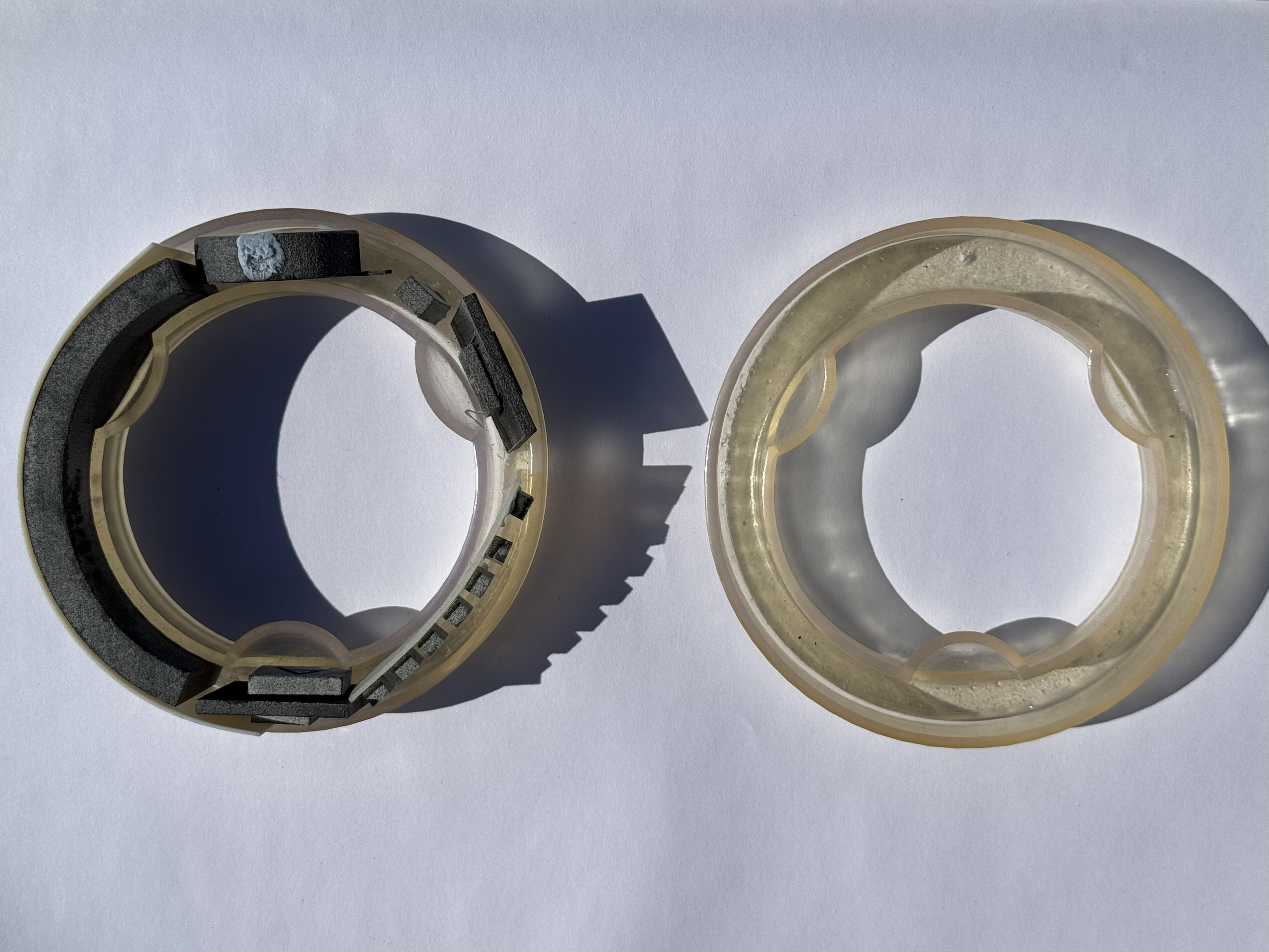
A big part of Oura’s design is, of course, the whole LED and photodetector setup for heart measurement, which included optical lenses made out of the ring’s housing.
From our own teardown, we additionally learned that:
- Induction charger used 6.8 MHz (half of 13.56 MHz, known for RFID)
- The charger base works by sensing the current in the coil. When the current gets low enough, the charger is going into “looking for a ring” state
- There is no communication between the charger and the ring; the only “information” is the load current of the ring, which affects the primary coil current
Amazon Echo Loop
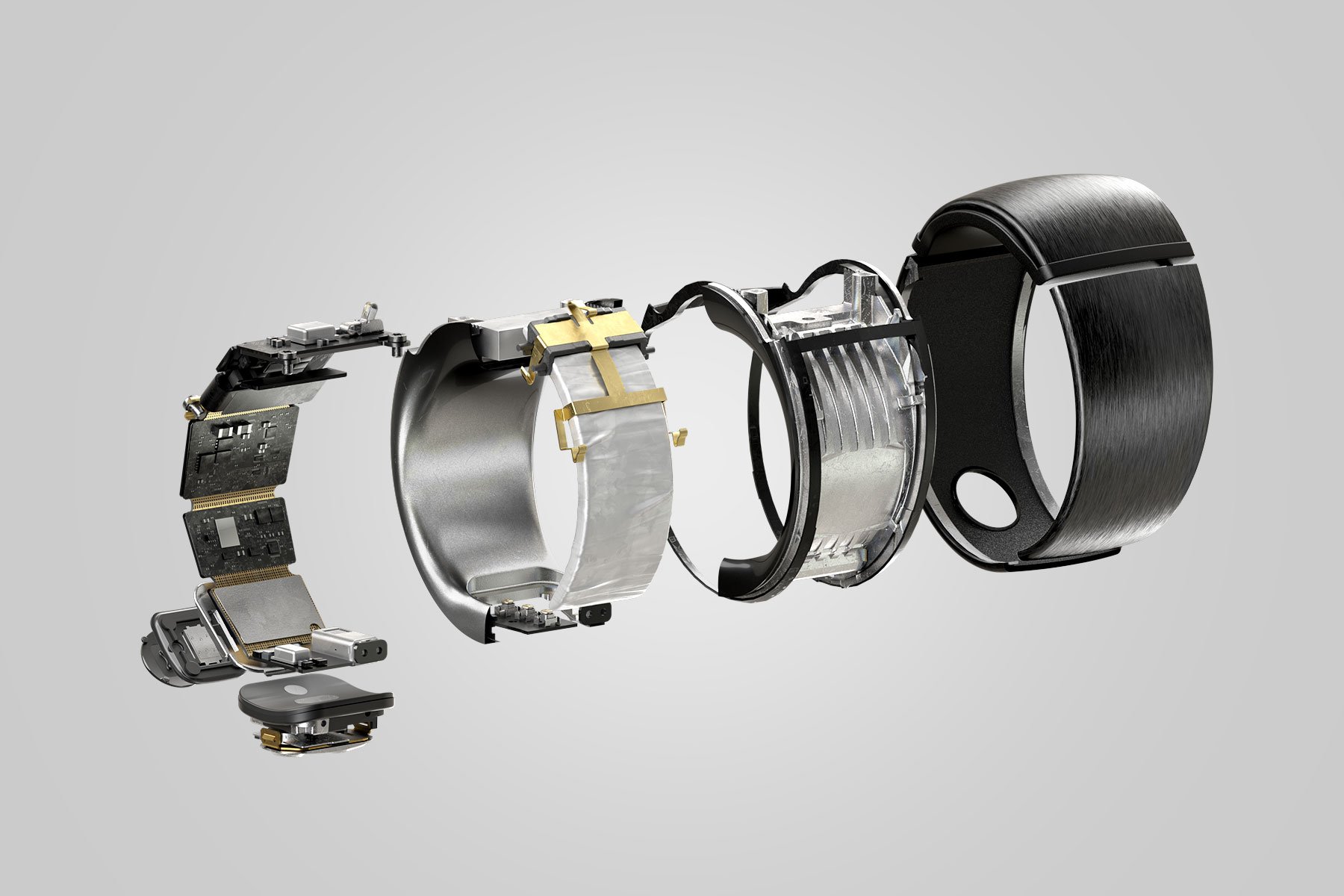
This ring from Amazon was discontinued shortly after launch. It was a really cool piece of tech as it allowed the user to talk to Alexa with their finger, so the hardware included a microphone, a speaker, and a Bluetooth audio chipset. It also featured innovative haptic feedback design using piezo.
Here’s an exploded photo of the ring from Amazon itself:
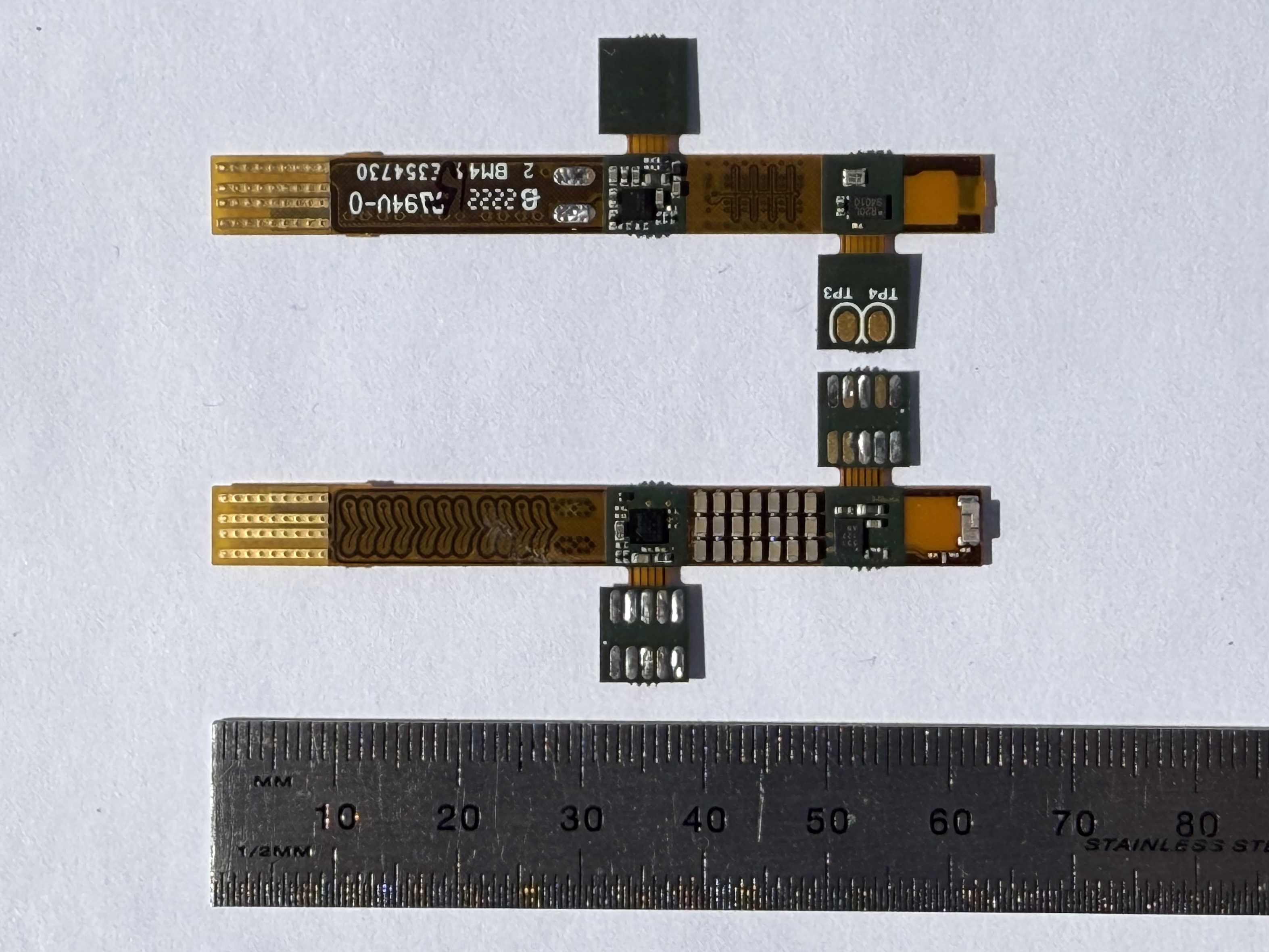
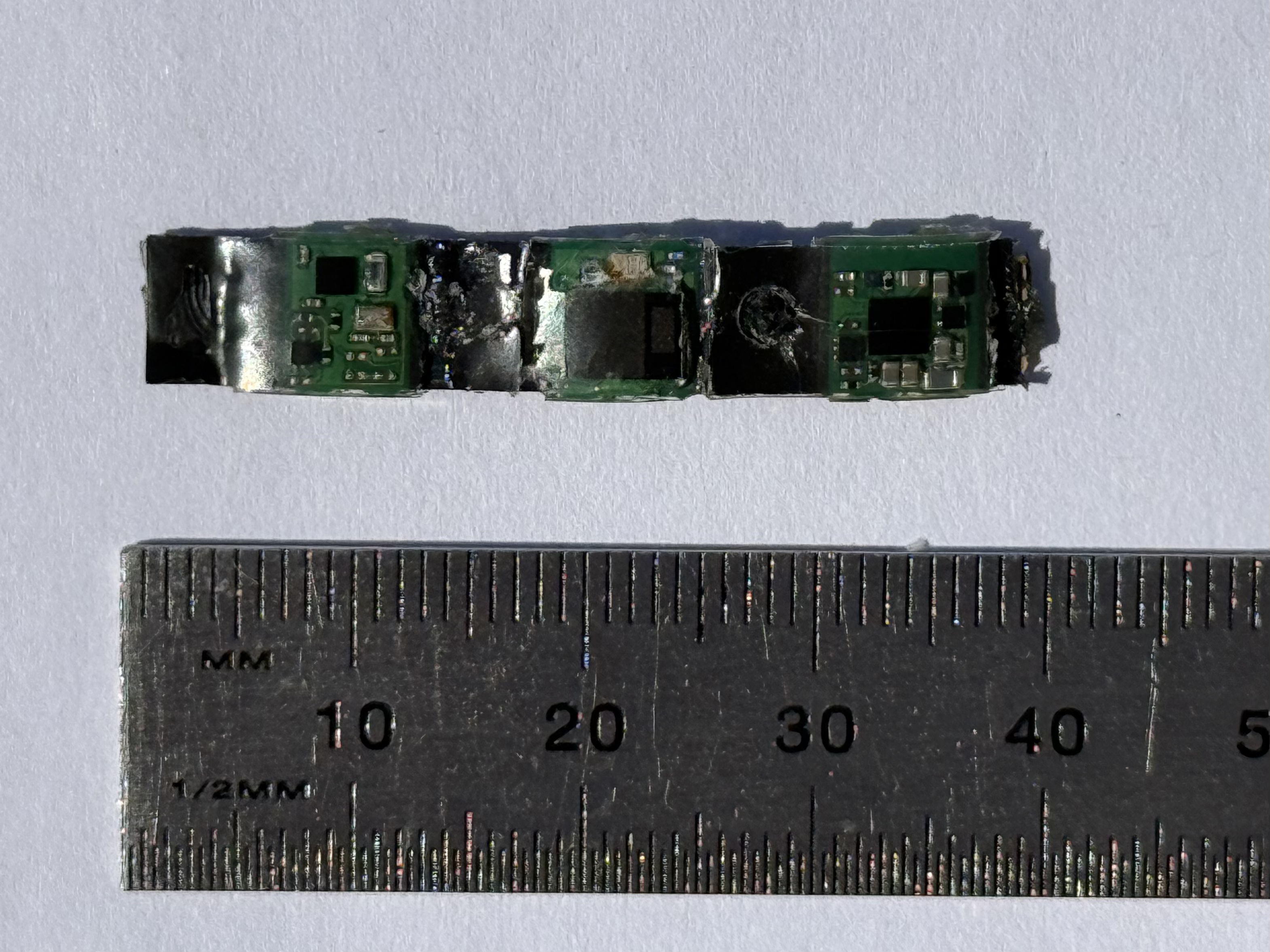
There were no known teardowns of this ring at the time, so we did our own:
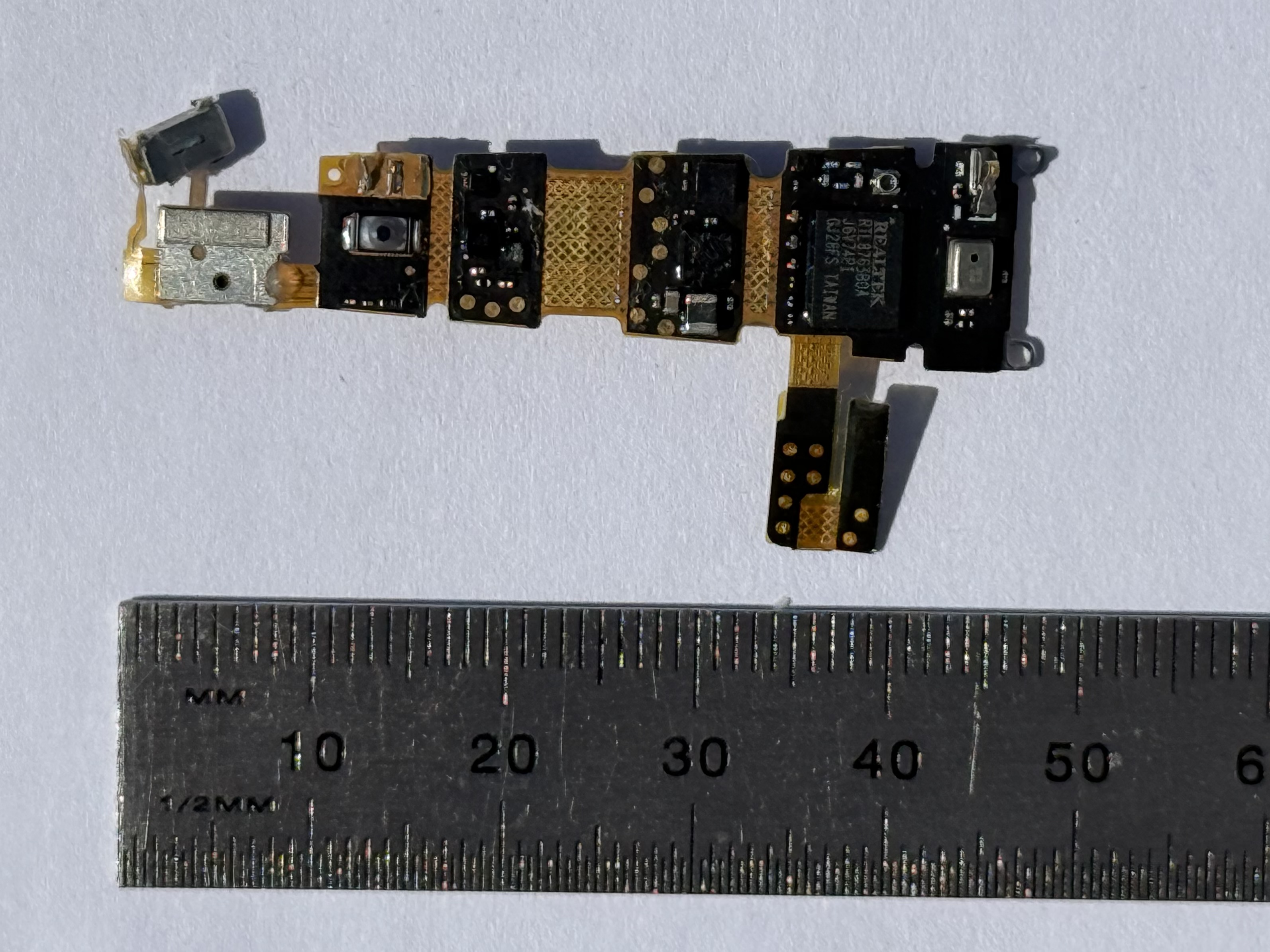
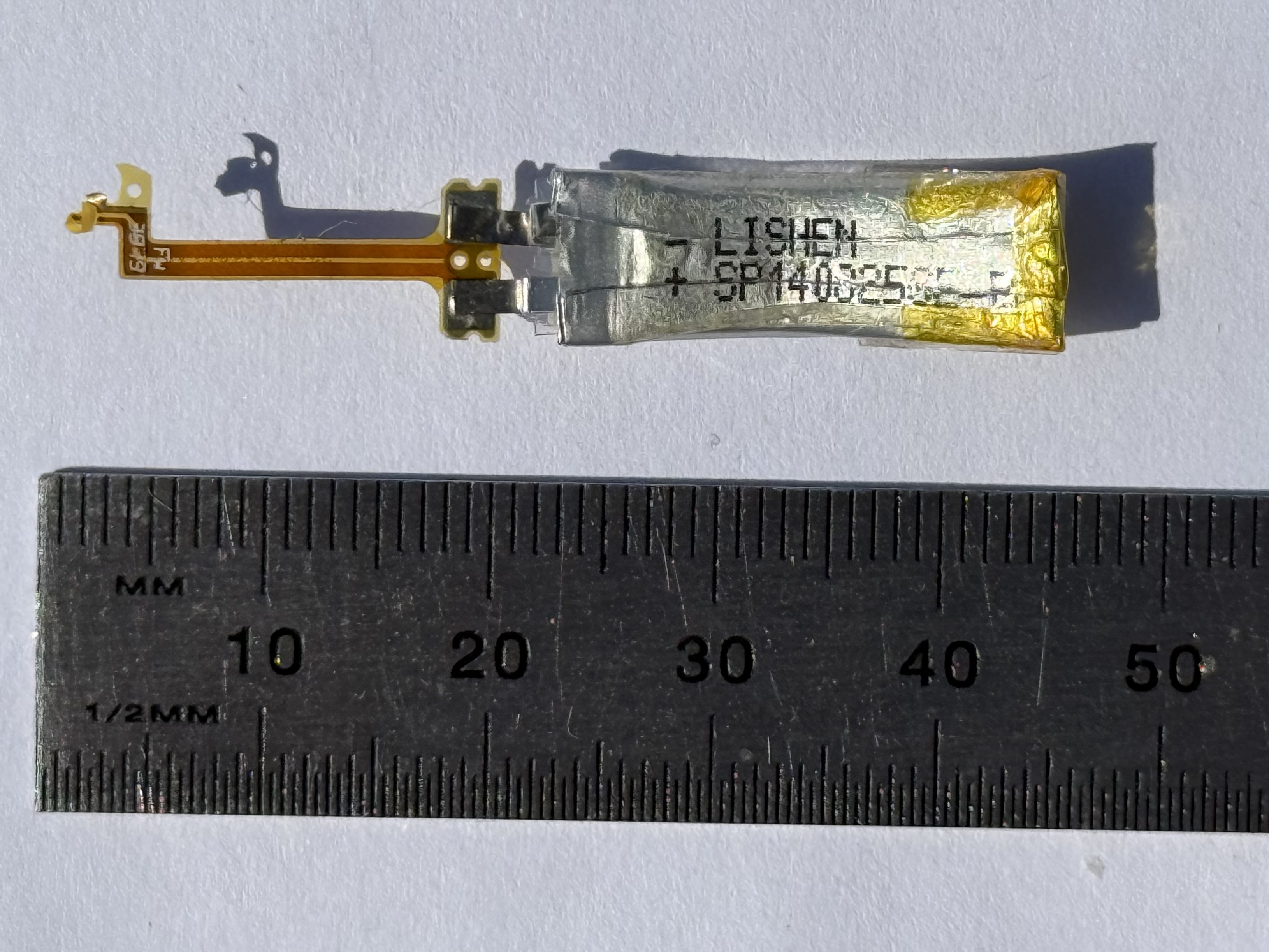
Learnings:
- Realtek RTL8763B0A SoC
- Micro antenna connector left on the PCB (must have been for testing)
- Lishen curved Li-Ion battery
- 3 contacts left for charging
- Custom piezoelectric haptic feedback design
The charger’s design for this ring was extremely simple, as Amazon decided to use contact charging, which is a no-brainer. The only problems with such a design are mechanical, wear and tear, and industrial design.
Prototype
Having learned a ton from other products in the market, it was time to put together a plan for making our own Smart Ring. Our requirements were:
- Normal-sized ring, similar to a typical wedding band (nothing bulky!)
- A touch pad for gestures
- Haptic feedback
- Induction charger
- Wear detection (for power saving)
- Lasting 2-3 days on a single charge with “normal” usage
The obvious problem was sizing. If space wasn’t a concern, creating such a product would be pretty easy, but fitting all of this inside a 2.6mm thick curved band was the real challenge. Not to mention, fingers come in different sizes, so we were looking at a product that comes in sizes from US 6 to US 13 (the standard for most population).
Without getting too deep (next article is about hardware design), we’ve built some single board prototypes for each of the requirements. For the touch pad, we settled on the Atmel SAM family as they came in WLCSP package and had mutual capacitive sense technology, which was needed as the ring has no “real” grounding (it’s floating relative to the battery). The induction charging part was quite easy as it was a simple flyback transformer with separated coils, with each coil being on a PCB and an air gap between them rather than a ferrite core.
Haptic feedback turned out to be the trickiest of them all. We couldn’t do a piezoelectric haptic design like Amazon did, as we didn’t have the funds to make a fully custom solution, so we were looking for off the shelf components only. Fortunately, we learned that coin vibration motors are made in very small sizes. They require high startup current (>150mA), which can be solved by adding lots of capacitance. Our final solution was a coin motor with enough capacitors to make it vibrate for one single “buzz”.
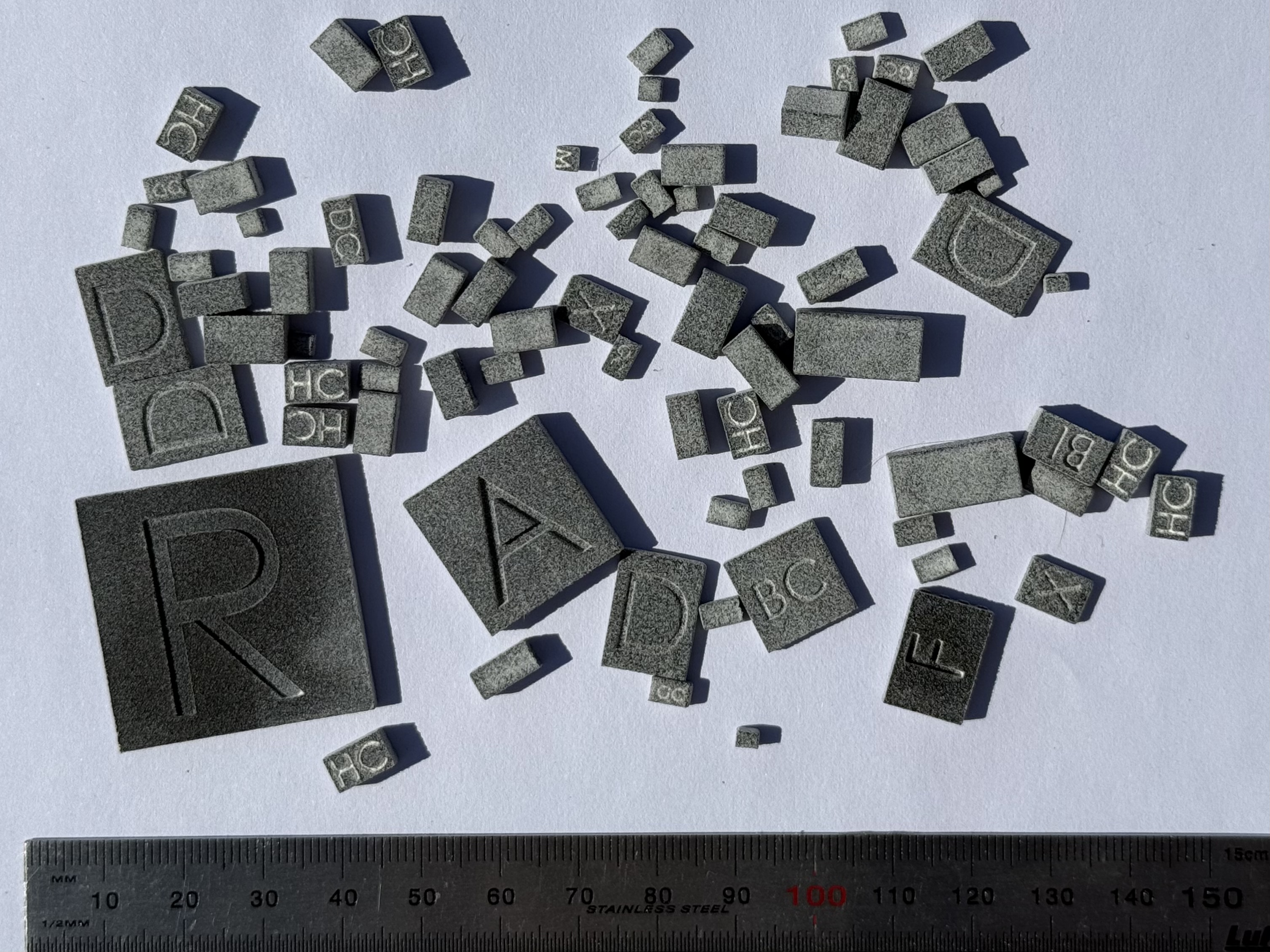
Fitting all these components in a Smart Ring factor seemed impossible until we came up with a clever idea to 3D print all the PCB components from their STLs and play with them like LEGO bricks to make it fit, which you can see in the pictures below:
Conclusion
Building a Smart Ring isn’t an easy task due to space requirements and tight coupling between electronics, mechanical design, and usability. In many ways, it’s similar to building a smartphone, where everything is carefully picked to fit together. It was the first project I worked on where every single chip had to be WLCSP or BGA, there was no space for legs sticking out of a package, and even QFN with no leads was too big! The PCB required a complex rigid-flex design with laser microvias, and every bit of it was routed with traces to get this product to work.
In the next article, we will dive into the hardware design of Open Ring, so stick around and read on!
See anything you'd like to change? Submit a pull request or open an issue on our GitHub
References
 Mikolaj Stawiski is a passionate software engineer coming from awesome electronics and hardware worlds.