LTE and IoT - How We Got Here
Cellular devices and networks have come a long way, from brick phones and Blackberrys to iPhones and Google Pixels. In addition to being the ubiquitous connectivity protocol that keeps the Internet at our fingertips at all times, LTE is appearing in IoT products across all industries. LTE modems now boast reduced power consumption and a more compact form factor than ever; coupled with the promises of 5G technology’s support for millions more connected devices, there is no doubt that this is an exciting time to be working on an LTE-enabled device!
Lately, I have been learning everything I can about LTE as it pertains to IoT systems, starting from the ground up. I had to start from scratch because this recent dive was my first real foray into cellular technology. I began with dumping acronym definitions in a doc (UE, GSM, LPWAN, E-UTRAN, PTW, MNO — there are so many! 😱) until I realized that weaving these together into a cohesive story would help me and perhaps some readers too.
In this article, I describe some of my findings from a recent investigation of how LTE technology was built for IoT systems. Complete with some history and a few diagrams to illustrate cellular network architecture and LTE power-saving features like eDRX and PSM, this read will give a nice introduction to LTE in embedded systems.
Table of Contents
A Brief History
To understand LTE, the standard backing 4G cellular networks, I wanted to understand some context around how the technology developed. Before LTE, cellular networks went through several evolutions, and I have captured roughly where each evolution falls in terms of data rates in the image below.
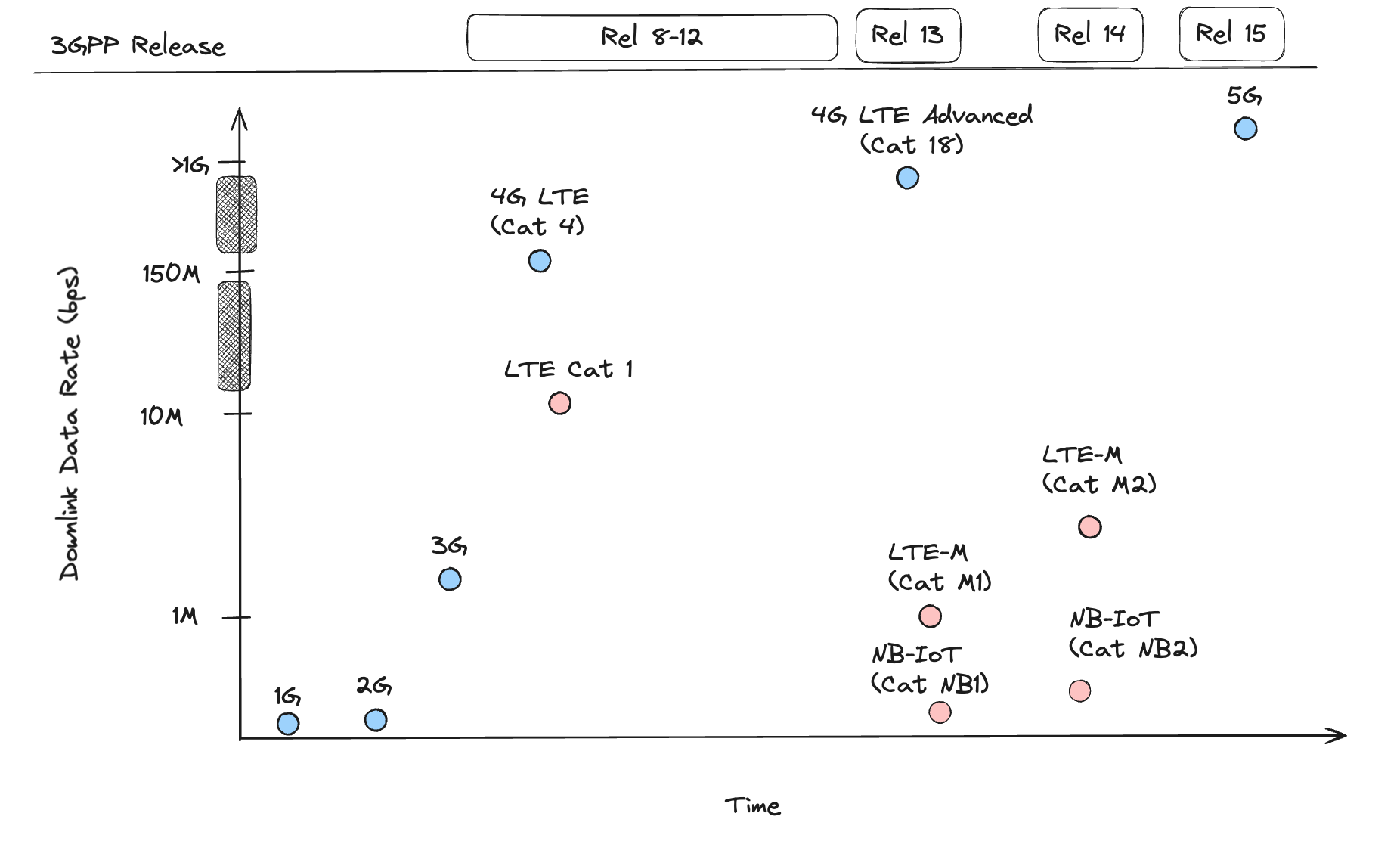
I had to bunch up the scale on the Y-axis to squeeze in 4G and 5G because the downlink speeds jumped so significantly! The standards relevant to today’s technology map to 3GPP releases starting with release 8. Those release specifications are available on 3PGG’s portal under the Specifications tab. A convenient link to all the 3GPP documents in the 36 series (the series on LTE) is available here, which is where I have been spending some quality time.
The first cellular network was launched in the 80s with just analog voice — no data. Then came the move to digital voice in the 90s, and a new network was created based on the GSM standard, which was labeled the 2G network, and its predecessor, the 1G. Data services also became available, enabling SMS text messaging and later, SMS’s extension, MMS, which enabled sending pictures, video, and audio. The first “high speed” mobile network arrived with the 3G network in the early 2000s, which was based on the UMTS standard and had rates around 2 Mbps.
IoT products started leveraging cellular networks for connectivity with the introduction of 2G and 3G data services. 2G and 3G provided an opportunity for devices with low bandwidth requirements; with 3G technology, transmitting too much data incurred a power cost that did not support the widespread use of battery-powered IoT devices with higher data requirements, like the advanced asset tracking applications we see today.
A different technology was necessary to support demands for increased data consumption by low-power IoT devices. Furthermore, the nature of IoT communication was fundamentally different than human-generated traffic; data packets are shorter, delays are acceptable, most traffic is uplink, and a massive amount of devices connect to a single station 1.
Enter LPWANs (Low Power Wide Area Networks), which use lower power communication protocols than traditional cellular connections. The major non-cellular-based technologies are Sigfox and LoRaWAN, which operate in unlicensed frequency bands 2. Sigfox started the development of LPWANs in 2010 3, two years after 3GPP (3rd Generation Partnership Project), an umbrella term for the organizations that develop mobile telecoms standards, launched the 4G network, which leverages the LTE (Long-Term Evolution) standard. 3GPP responded to the competing LPWANs and the market demand in 2013 with the development of LTE-based LPWAN technologies: LTE-M and NB-IoT.
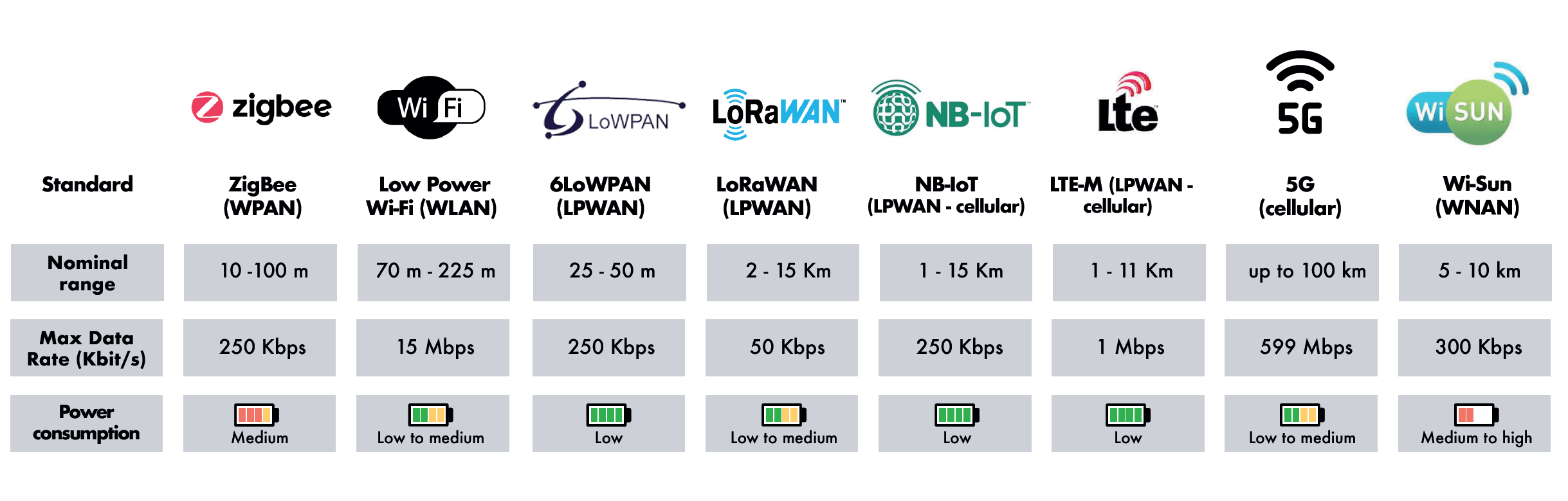
An alternative standard that could work for some IoT applications, LTE Cat 1, is the first or lowest category of LTE with a throughput cap of 10 Mpbs for download and 5 Mpbs for upload and reasonably low power consumption 4. The advantage of LTE Cat 1 over LTE-M and NB-IoT is that it uses the same standard as LTE while LTE-M and NB-IoT are different standards. As a result, LTE-M and NB-IoT require new technology in networks that support them, and the rollout has been slower than expected. A regularly updated map is available here from GSMA depicting the coverage of LTE-M and NB-IoT worldwide; some countries only support one of the two. Finally, for some context on how LTE technologies like LTE-M and NB-IoT stack up in range, max data rate, and relative power consumption compared to other popular IoT connectivity protocols, below is a table from Saft Batteries 5 that gives a nice summary.
Before zooming in on how LTE-M and NB-IoT work, let us first zoom out and take a look at how networks are structured.
Cells, UEs, and eNBs
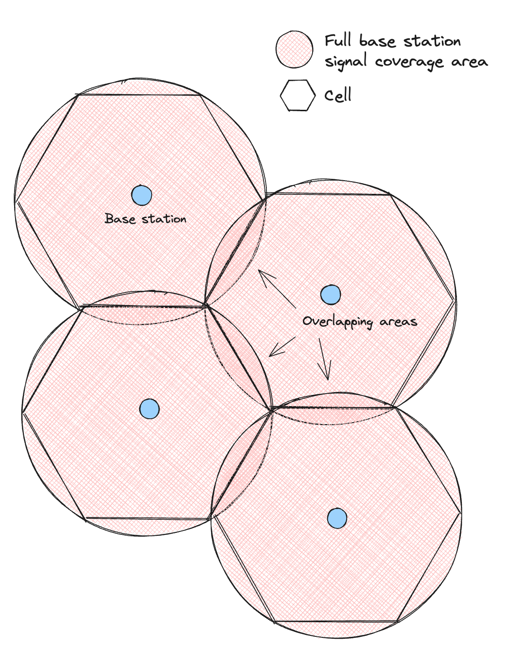
The word cell in cellular and cell phone comes from the network architecture – a fact which I vaguely understood before but did not fully comprehend. Cellular networks are composed of cells organized in a hexagonal pattern covering a geographic area. At the center of a cell is a base station with a transceiver, which provides network coverage to a cell. In other words, a cell is the coverage area of a base station.
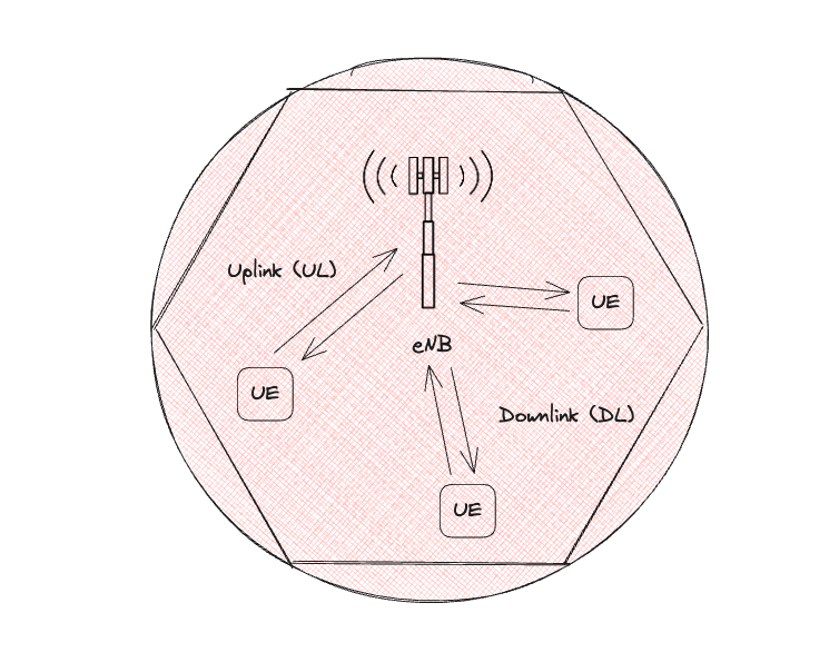
In LTE networks, a cellular-enabled device called the User Equipment (UE) connects to a base station called the evolved Node B (eNB). The signal traveling to the eNB is the Uplink (UL) signal, while the signal traveling to the UE is the Downlink (DL) signal. The UE, eNB, and E-UTRA (Evolved UMTS Terrestrial Radio Access), the wireless communication technology used in LTE networks, all make up what is called the E-UTRAN (Evolved UMTS Terrestrial Radio Access Network). This network is distinct from another entity, the Evolved Packet Core (EPC), which connects the radio access network to the Internet. Radio Resource Control (RRC) is the physical layer protocol of the E-UTRAN, and is used for communication between the UE and eNB. Two RRC states, idle and connected, will play a role in power save modes.
Why hexagons? 🤔 While coverage from the transceiver’s radio is circular, dividing up an area via circles would result in overlapping areas, so the abstraction of another shape is needed to represent coverage better and optimize for fewer base stations when laying out stations. To minimize the number of base stations, the shape chosen should maximize the area of the base station it is centered around. Of all the basic shapes, Hexagons take up the greatest percentage of a circle. Note there is still overlapping in regions where signals from two neighboring cells are available. Still, the area of these overlapping regions is smallest when using hexagons to organize stations.
Low-power Technologies
LTE-M and NB-IoT are the two primary cellular-based LPWAN standards. LTE-M, an abbreviation for LTE-MTC (Machine Type Communication), is more expensive but is better for devices requiring higher data rates. While differing in the environments and applications they are used in, they both support two modes that enable low-power behavior: eDRX (extended Discontinuous Reception) and PSM (Power Save Mode). They can be used together since they manage different parts of a cellular connection.
The power savings of these modes rely on two key factors:
- Being able to maintain “attached” to the network. Attaching is a very high-power procedure
- Being able to switch off the radio while in sleep or idle states. Turning on the radio is also high power
This first point about network attachment is key and explains why simply turning off the modem can hurt a device’s power budget.
To stay attached to the network, a UE enters RRC Idle mode, during which the device listens for paging updates from the eNB (eDRX mode), and/or turns the radio completely off before waking up to give the eNB a tracking area update (PSM TAU value). After it wakes up, it enters RRC Connected mode, and UL and DL data are sent to/from the eNB. While learning about these power save modes, I put together a diagram to keep track of the relative power consumption of each, as well as the changes in the radio and RRC states (a lot is going on!).
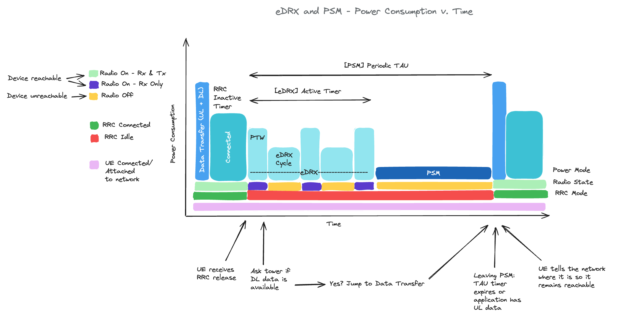
eDRX
DRX is a mode that allows more fine-tuning of the intervals at which a device switches from unreachable to reachable. eDRx enables longer DRX cycle length (sleep time), which is crucial for IoT systems that prioritize power savings over constant connectivity. In regular DRX, sleep time is only around 2.5 seconds whereas eDRX can be up to 43 minutes 6. During this interval, the UE is not reachable by the network. The Paging Time Window (PTW) is the period when the UE is reachable by the network and when it can communicate with the network.
Modems in eDRX tend to have a current draw in deep sleep on the order of 10-30 µA. I have recently been working with Nordic’s nRF9160 modem, so I will use figures from that data sheet as an example for comparing current draw and wake-up times. The nRF91 modem’s current draw during sleep with an eDRX interval at 82.91s at 3.7 V is 8 µA for LTE-M and 37 µA for NB-IoT 7. For both standards, the nRF91 takes about 1 ms to wake up and start receiving data 8.
Some cellular modems allow you to set both the PTW and eDRX Cycle, but some modems only allow you to set the eDRX cycle. You will need to study the AT Commands manual from your cellular modem vendor to find out what applies to your modem.
PSM
PSM requires very little power compared to eDRX. The device remains registered in the network, but the radio is off, therefore it does not transmit or receive data and cannot be reached from the outside. However, for a device to stay connected to the network, it must wake up periodically to update the network on its location. This interval is called the Periodic TAU, during which the UE will stay in power-saving mode before waking up to send a Tracking Area Update (TAU) to the network.
Modems in PSM have a current draw on the order of a few microamps. The nRF91 modem’s current draw during sleep is about 2.7 µA at 3.7 V for both standards. The modem takes ~100-200 ms to wake up and receive data, a marked increase from waking up from eDRX.
PSM is a good option for systems that can tolerate higher latency and have stricter power requirements because it has a lower power draw in its deep sleep mode. However, it will not respond for the duration of its sleep, and it takes longer to get out of that sleep mode. For systems that need more frequent check-ins with the network but need more power savings than leaving the modem in the regular RRC Connected state, eDRX is the better option because it checks for data from the network more frequently and connects to the network faster coming out of sleep.
Conclusion
I have barely scratched the surface of how LTE works for IoT systems! However, with some fundamentals like the history of cellular standards, cellular network architecture, an understanding of LTE power-save modes, and a handful of acronyms, the rest is much easier to wade through.
I am always eager to gain insights into details I might have overlooked, as well as hear about your experience learning about and working with LTE. Engage with me in the comments, or connect with me on the Interrupt Slack community for a more extensive discussion!
References
 Gillian Minnehan is a firmware solutions architect at Memfault. Gillian previously worked on embedded software teams in space and defense.