Securing Firmware Updates With AES Encryption
Connected devices require a secure point-to-point channel to ensure that there is no possibility of exposing important data for the integrity of an embedded system. This is especially true when we talk about over-the-air (OTA) software updates, where the new firmware has a long way to go before reaching its destination and being installed by our bootloader.
In this publication, we will explore a simple method to encrypt the firmware using the AES algorithm, using open-source libraries in Python. Of course, we will also see how to decrypt the firmware from the MCU using the AES encryption engine.
Table of Contents
Firmware Encryption Explained
Encryption is a process of encoding information, specifically applied to firmware, which involves converting the original firmware image plaintext into an alternative form ciphertext. Authorized parties who possess the encryption key can decrypt the ciphertext back into plaintext and access the original information.
When performing firmware updates with security in mind, it is important to consider the authenticity and confidentiality of our firmware. Encrypting the firmware is a way to enhance the confidentiality of our update system. Let’s see when it is advisable to implement firmware encryption.
Why encrypt our firmware
When performing updates via OTA, it is crucial to consider that our firmware is exposed to various methods of firmware extraction, such as:
- Sniffing the OTA: An attacker can intercept the binary firmware while the device is undergoing an update.
- Reading the firmware from UART, JTAG, or the device’s flash chip: Attackers may attempt to extract the firmware by accessing these interfaces.
- Intercepting the firmware during the download process: If the firmware is downloaded for device update over unencrypted HTTP traffic, an attacker could intercept it.
Considering these scenarios, it becomes necessary to add security mechanisms to our update system, such as signing or encrypting the firmware image. These measures help ensure the integrity and confidentiality of the firmware during the update process, mitigating the risk of unauthorized access or tampering.
When to use firmware encryption
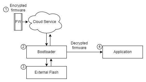
Indeed, protecting firmware is important, but it’s essential to analyze certain factors before considering firmware encryption. Firmware encryption may not be necessary for all systems. The primary purpose of employing firmware encryption is to add confidentiality while transporting the firmware to the device or while it resides in an external flash memory.
Firmware encryption is necessary when:
- The messages sent from the server to the device are not encrypted.
- The bootloader has secure storage to protect the encryption key.
- The bootloader installs the new firmware in an external flash memory.
- The bootloader extracts the firmware from the external flash memory to install it in the internal application flash memory.
Points to consider when firmware encryption is necessary:
| Points | Explanation | Firmware Encryption |
|---|---|---|
| 1 3 | The firmware image is exposed from the server to the device and from external flash | ✅ |
| 3 4 | The firmware image can be extracted from external flash | ✅ |
| 2 3 | The firmware can be extracted from external flash we can store decryption keys in secure storage | ✅ |
| 2 4 | The firmware can be extracted from external flash we can store decryption keys in secure storage | ✅ |
Firmware encryption is not necessary when:
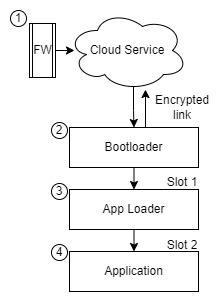
- The communication link between the server and the device is already encrypted, for example, using TLS (Transport Layer Security). You can authenticate client and device connections with X.509 certificates.
- The bootloader performs authenticity and integrity validation on the firmware image using code signing, CRC validation, and a metadata header.
- The Loader can be used to update and install new firmware images or update the bootloader in case changes to the validation process in firmware images are required.
- The firmware image boots only if it is validated for authenticity and integrity when installed and at each boot.
Points to consider when firmware encryption is not necessary:
| Points | Explanation | Firmware Encryption |
|---|---|---|
| 1 2 | From the server to the device the data is encrypted thanks to the protocol used | ❌ |
| 2 3 | Validation mechanisms can detect changes in firmware integrity | ❌ |
| 2 4 | Integrity validation mechanisms can detect firmware changes and reject that firmware image | ❌ |
| 1 3 | Encrypted data from server to device and also having a code signature is a good combination | ❌ |
In this case, if the communication link is already secured, and the bootloader and Loader ensure the integrity of the firmware through code signing, the need for additional firmware encryption may be reduced. However, it’s essential to thoroughly assess the security requirements of your specific system and consider factors such as the sensitivity of the firmware and potential attack vectors to make an informed decision regarding firmware encryption.
Certainly, if you have the option to use a recommended bootloader like MCUBoot1 that supports firmware image encryption, it is highly advisable to utilize it. However, if you need to implement a custom bootloader, this publication aims to serve as a starting point for implementing firmware image encryption.
AES
AES (Advanced Encryption Standard) is a symmetric key cryptographic algorithm, meaning the same key is used for both encryption and decryption of the message. The algorithm offers various modes such as CBC (Cipher Block Chaining), ECB (Electronic Codebook), CTR (Counter), and CCM (Counter with CBC-MAC), each with different characteristics. In this publication, we will focus on the CTR mode for several reasons:
- Security: CTR mode is considered one of the most secure AES modes2.
- Popularity: It is widely used because it allows encrypting/decrypting any block without the need to know any other block. This mode is employed in MCUBoot3.
- Availability: Most AES encryption engines within MCUs can work with this mode.
- Small footprint: CTR mode does not impose a heavy resource burden on MCUs or cryptographic libraries4.
While the mathematics behind the AES-CTR algorithm are beyond the scope of this publication, let’s discuss the key points to understand the encryption process.
CTR Mode
CTR mode, also known as Counter mode, is a stream cipher mode of AES encryption. With stream cipher encryption, it is not necessary to encrypt the plaintext in fixed blocks like AES in CBC mode, which encrypts data in 16-byte blocks. If the plaintext to be encrypted is smaller than the block size, padding is required to process a complete 16-byte block.
In contrast, CTR mode performs the encryption of plaintext on a per-byte basis using the corresponding digit of the key stream. Let’s take a moment to define what the key stream is essentially a stream of characters used to obtain the ciphertext. In each iteration, a new key stream is generated by encrypting successive values like a counter.
In CTR mode, the encryption process involves:
- Generating the key stream by encrypting successive counter values.
- XORing each byte of the plaintext with the corresponding byte of the key stream.
- Obtaining the ciphertext by repeating this process for each byte of the plaintext.
Since CTR mode operates on a per-byte basis, it offers more flexibility and efficiency when encrypting data of varying sizes, as there is no need for padding. Additionally, it allows for parallelization and random access to encrypted data, making it a popular choice for many applications, including firmware encryption:
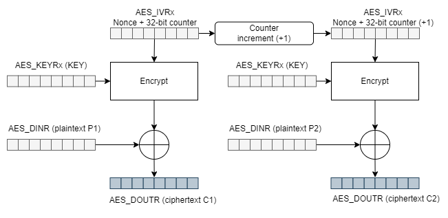
Now we know that we need a key stream to begin encrypting the first data, and then a new key stream will be generated in the form of a counter for each subsequent encryption operation until all the plaintext is encrypted.
We can see that we need a couple of inputs:
- (AES_KEYRx (KEY)): For encryption and decryption, we will refer to the value as the
Keyvalue. - (AES_IVRx): In CTR mode, the initialization vector is also referred to as the counter, which we will identify as the
Nonce.
Before moving on to implementation, let’s review some important points:
- CTR mode requires a
Keyand an initialization vectorNonce. - We can encrypt plaintext data (AES_DINR (plaintext P1)) in blocks of various sizes, for example, 4 bytes at a time.
- Each time we encrypt a plaintext block, the counter block increases by one unit.
- The counter block
Nonceis the concatenation of a fixed Nonce block, set during initialization, and a 32-bit counter variable.
By understanding these key points, we can proceed with the implementation of CTR mode encryption.
Firmware Encryption Implementation
To begin with, the implementation, let’s use the PyCryptodome5 cryptographic library to create a Python script that takes our firmware file and generates a new encrypted output file. First, let’s install the PyCryptodome library in Python. You can install it by running the following command:
pip install pycryptodome
Define encryption keys
To define the encryption keys, we will generate a key to use in the script using the PyCryptodome library. This same key will also be used for decryption in the MCU. For our configuration, we will use AES-128, which requires a 16-byte key. Additionally, we will use a 2-byte Nonce value as the initialization vector.
from Crypto import Random
myKey = Random.get_random_bytes(16)
myIV  = Random.get_random_bytes(2)
print(myKey.hex())
print(myIV.hex())
Here are the generated keys:
583bf4901f623510a1408e8be7bd6f5a
f824
Encrypting with PyCryptodome
Let’s use the generated keys to start encrypting data. The first step is to configure our counter block, which is a necessary parameter to create an object that allows us to encrypt using the .encrypt() method.
Counter Block
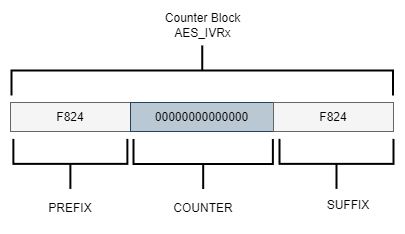
According to the PyCryptodome documentation5, we can create a counter block by concatenating values before (prefix) and after (suffix) the counter variable:
Let’s use our key and Nonce value to create the counter block using the Counter.new() method. The method requires several parameters:
- The desired counter length in bits.
- The initial value of the counter.
- The endianness of the counter data alignment.
counter length: 112 bit / 8 = 14 bytes counter block length: 14 bytes + Nonce 2 bytes = 16 bytes = 128 bit
Since we want a counter length of 112 bits and our Nonce is 2 bytes, the counter block length should be 16 bytes (128 bits) to match the AES-128-bit encryption. We want the counter variable to start at 0, so we’ll set initial_value=0. We’ll also specify little_endian=False for big-endian data alignment to align with the counter in the AES processor on the MCU:
import binascii
from Crypto.Cipher import AES
from Crypto.Util import Counter
myKey = "58:3b:f4:90:1f:62:35:10:a1:40:8e:8b:e7:bd:6f:5a"
myIV  = "f8:24"
AES_KEY = binascii.unhexlify(myKey.replace(":", ""))
AES_NONCE = binascii.unhexlify(myIV.replace(":", ""))
blockCounter = Counter.new(112, prefix=AES_NONCE, little_endian=False, initial_value=0)
print( blockCounter )
We see the parameters of the counter block:
{'counter_len': 14, 'prefix': b'\xf8$', 'suffix': b'', 'initial_value': 0, 'little_endian': False}
The result should look something like this:
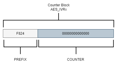
The size of the Nonce (PREFIX) impacts the amount of space available for the counter variable. A larger Nonce value means less space is available for the counter. For instance, if a 4-byte Nonce is generated, the remaining 12 bytes will be used for the counter.
It’s important to consider the size of the counter variable because if a significant amount of data is encrypted and the counter variable size is not sufficiently large, it may overflow. The library will raise an OverflowError exception as soon as the counter wraps back to its original value.
To address this, one approach is to leave the Nonce value empty, allowing the counter variable to have more space. This allows us to encrypt a larger number of data blocks. Since the Nonce value and the counter block share the same space, it needs to be aligned to 16 bytes.
Encrypt script
To encrypt a firmware file using the defined Key and initialization vector Nonce, you can create a script that performs encryption on a firmware file in the .bin format. The manipulation of the firmware binary file can be done using a class that reads the file in blocks of 4 bytes:
class BinaryFile:
    def __init__(self, nameFile, mode):
        self.openFileName = nameFile
        try:
            self.ObjectFile = open(self.openFileName , mode)
        except IOError:
            print("Cannot open binary file \n")
            print("Make sure it is in the same folder as the script\r\n")
            sys.exit(1)
    def CloseFile(self):
        self.ObjectFile.close()
    def ReadFile(self, numberBytes):
        return self.ObjectFile.read(numberBytes)
    def WriteFile(self, dataBytes):
        self.ObjectFile.write(bytes(dataBytes))
    def SizeFile(self):
        return os.path.getsize( self.openFileName )
To encrypt, a class is created where the counter is initialized and a SwapLittleEndian method is also added to perform an exchange in the data format since our MCU handles the data in Little Endian format, this is important because if this exchange is not carried out in the format we won’t get the same result when decrypting from MCU:
class  EncryptionCTR:
    def __init__(self, key, iv ):
        self.key = binascii.unhexlify(key.replace(":", ""))
        self.iv  = binascii.unhexlify(iv.replace(":", ""))
        self.count_ctr = Counter.new(112, prefix=self.iv, little_endian=False, initial_value=0)
        self.cipherObject = AES.new(self.key, AES.MODE_CTR, counter=self.count_ctr)
    def EncryptCtr(self, plaintext):
        return self.cipherObject.encrypt(bytes(plaintext))
    def SwapLittleEndian(self,plaintext):
        temp_swap = [bytes]*BYTES_READ
        temp_swap[0] = plaintext[3]
        temp_swap[1] = plaintext[2]
        temp_swap[2] = plaintext[1]
        temp_swap[3] = plaintext[0]
        return temp_swap
The script needs the name of the app.bin firmware binary file to be encrypted and a name for a new file that corresponds to the encrypted firmware Cipherapp.bin. A 4-byte read of the original plaintext firmware file is performed, the format exchange is performed, we encrypt the block and finally, the ciphertext block is written to a new binary file:
def main():
    print(__name__)

    PlainFirmware  = BinaryFile(sys.argv[1],'rb')
    CipherFirmware = BinaryFile(sys.argv[2],'wb')
    CryptoFirmware  = EncryptionCTR(mykey,myiv)
    bytes_remaining = 0
    bytes_so_far_cryted = 0
    BinaryFileSize = PlainFirmware.SizeFile()
    bytes_remaining = BinaryFileSize - bytes_so_far_cryted
    print("Bytes to encrypt :{}", bytes_remaining )
    while(bytes_remaining):
        Plainbytes = PlainFirmware.ReadFile(BYTES_READ)
        PlainbytesLittle = CryptoFirmware.SwapLittleEndian(Plainbytes)
        Cipherbytes = CryptoFirmware.EncryptCtr(PlainbytesLittle)
        CipherbytesLittle = CryptoFirmware.SwapLittleEndian(Cipherbytes)
        CipherFirmware.WriteFile(CipherbytesLittle)
        print( PlainbytesLittle )
        print( CipherbytesLittle )

        bytes_so_far_cryted += BYTES_READ
        bytes_remaining = BinaryFileSize - bytes_so_far_cryted
        if( bytes_remaining <= 0 ): bytes_remaining = 0
        print( bytes_remaining )

    PlainFirmware.CloseFile()
    CipherFirmware.CloseFile()
main()
Firmware Decryption Implementation
We have successfully received the encrypted firmware through our update system. Now, the responsibility lies with our MCU to decrypt the firmware and install it in a flash memory section where the bootloader can execute it. In this particular post, we will be utilizing the AES hardware accelerator present in ST Micro’s STM32L4S5 MCU to carry out the firmware decryption process. All code mentioned in this post is specifically written for the development kit B-L4S5I-IOT01A6.
Define encryption keys
Remember that AES is a symmetric key algorithm so it is no longer necessary to generate new keys to decrypt, we have to use the same keys used to encrypt. Let’s define the initialization vector and the key:
static const uint8_t pKeyAES[16] __attribute__ ((aligned (4))) = {
                            0x58,0x3b,0xf4,0x90,0x1f,0x62,0x35,0x10,0xa1,0x40,
                            0x8e,0x8b,0xe7,0xbd,0x6f,0x5a};
static const uint8_t NonceAES[16] __attribute__ ((aligned (4))) = {
                            0xf8,0x24,0x00,0x00,0x00,0x00,0x00,0x00,0x00,0x00,
                            0x00,0x00,0x00,0x00,0x00};
Decryption with AES hardware accelerator
The AES hardware accelerator encrypts and decrypts data and supports CTR mode, for 128-bit or 256-bit key sizes. It is necessary to configure the peripheral according to how we encrypt the firmware to be sure of obtaining the same result when decrypting.
So we need to make a configuration with these points:
- Decryption with chaining mode Counter (CTR) mode.
- Key sizes of 128 bits.
Let’s see how the hardware accelerator processes a message when it works in CTR mode presenting a structure similar to the one we defined when encrypting:
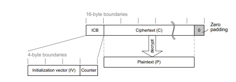
The structure of this message is:
- A 16-byte initial counter block (ICB), composed of two distinct fields:
- Initialization vector (IV): a 96-bit value that must be unique for each encryption cycle with a given key.
- Counter: a 32-bit big-endian integer that is incremented each time a block processing is completed. The initial value of the counter must be set to 1.
- The plaintext P is encrypted as ciphertext C, with a known length. This length can be non-multiple of 16 bytes, in which case a plaintext padding is required.
Setup AES hardware accelerator
After obtaining the required parameters, we can proceed to load the configuration into the CR register. Additionally, we need to initialize the key and initialization vector in their respective Nonce registers. The reference manual7 provides information about the configuration parameters, which can be accessed in section 34.7.1 of the AES control register (AES_CR).
void aes_setup( void ) {
    uint32_t keyaddr;
    uint32_t Nonce;
    //! Enable source clock for  AES peripheral
    RCC->AHB2ENR |= RCC_AHB2ENR_AESEN;
    //! Disable the AES peripheral
    AES->CR &= ~AES_CR_EN;
    //! Select the mode CTR
    AES->CR |= AES_CR_CHMOD_1;
    //! Select the mode of decryption
    AES->CR |= AES_CR_MODE_1;
    //! Select the Data type 8-bit
    AES->CR |= AES_CR_DATATYPE_1;

    //! Set the key, for default key size it's 128 bits
    keyaddr = (uint32_t)(pKeyAES);
    AES->KEYR3 = __REV(*(uint32_t*)(keyaddr));
    keyaddr += 4;
    AES->KEYR2 = __REV(*(uint32_t*)(keyaddr));
    keyaddr += 4;
    AES->KEYR1 = __REV(*(uint32_t*)(keyaddr));
    keyaddr += 4;
    AES->KEYR0  = __REV(*(uint32_t*)(keyaddr));
    //! Set the Nonce InitVector/InitCounter
    Nonce = (uint32_t)(NonceAES);
    AES->IVR3 = __REV(*(uint32_t*)(Nonce));
    Nonce += 4;
    AES->IVR2 = __REV(*(uint32_t*)(Nonce));
    Nonce += 4;
    AES->IVR1 = __REV(*(uint32_t*)(Nonce));
    Nonce += 4;
    AES->IVR0 = __REV(*(uint32_t*)(Nonce));
    //! Enable the AES peripheral
    AES->CR |=  AES_CR_EN;
}
Decrypt data
Once the configuration is set up properly, we can start decrypting blocks of 16 bytes of data. To achieve this, we input the data into the DINR register and obtain the plain text by reading the DOUTR register. For more information, please refer to section 34.7.3 (AES data input register - AES_DINR) and section 34.7.4 (AES data output register - AES_DOUTR) of the reference manual7.
void aes_decryption( uint8_t *Input_CipherFirmware, uint16_t buf_size, uint8_t *Out_PlainFirmware ) {
    uint32_t inputaddr  = (uint32_t)Input_CipherFirmware;
    uint32_t outputaddr = (uint32_t)Out_PlainFirmware;
    for( uint32_t idx = 0; idx < buf_size; idx += 16 ){
        //! Write the ChipherText in the input register DINR
        AES->DINR = *(uint32_t*)(inputaddr);
        inputaddr += 4;
        AES->DINR = *(uint32_t*)(inputaddr);
        inputaddr += 4;
        AES->DINR = *(uint32_t*)(inputaddr);
        inputaddr += 4;
        AES->DINR = *(uint32_t*)(inputaddr);
        inputaddr += 4;
        //! Computation completed flag
        while( (AES->SR & AES_SR_CCF) == 0);
        //! Clear the completed flag
        AES->CR |= AES_CR_CCFC;
        //! Read the PainText from the output register DOUTR
        *(uint32_t*)(outputaddr) = AES->DOUTR;
        outputaddr+=4U;
        *(uint32_t*)(outputaddr) = AES->DOUTR;
        outputaddr+=4U;
        *(uint32_t*)(outputaddr) = AES->DOUTR;
        outputaddr+=4U;
        *(uint32_t*)(outputaddr) = AES->DOUTR;
        outputaddr+=4U;
    }
}
Example architecture code
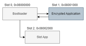
It’s time to see everything in action in the example code we have a fairly simple architecture with a boot loader boot.c and an application app.c.
The bootloader checks if something exists in slot 1 where the encrypted firmware application was installed. If the firmware image exists in Flash, it will proceed to decrypt and install it in slot 2 when finished, it will start the application.
Toolchain
The full example is available on GitHub at interrupt@fwup-encryption.
The following tools to compile and flash the firmware:
- B-L4S5I-IOT01A6
- GNU Make 3.81 as the build system
- arm-none-eabi-gcc version 10.3.1 20210824 (release) as compiler
- python 3.9.11
- SEGGER J-Link
Building & Running the Example
The project will build an application binary app.bin where you simply change the state of a GPIO. It will also build a binary file for boot.bin which performs firmware decryption and read and write flash memory.
Let’s start by building the project with make:
$ make
Compiling app.c
Compiling system_app.c
Compiling startup_app.s
Linking library app
Memory region         Used Size  Region Size  %age Used
             RAM:        2640 B       640 KB      0.40%
             ROM:        2176 B         4 KB     53.13%
Generated build/app.elf
Compiling boot.c
Compiling system_boot.c
Compiling Decrypting-EngineAES/aes_ctr.c
Compiling Decrypting-EngineAES/flash.c
Linking library boot
Memory region         Used Size  Region Size  %age Used
             RAM:        2672 B       640 KB      0.41%
             ROM:        2988 B         4 KB     72.95%
Generated build/boot.elf
$
In the Encrypting-PythonAES directory there is the Python Script to encrypt the firmware, after compiling in the build directory we have the application firmware called app.bin, we will start the python script from make so that the encryption of our image is performed:
$ make encryption
__main__
Bytes to encrypt :{} 2176
[32, 10, 0, 0]
[140, 151, 243, 6]
2172
[8, 0, 35, 217]
[133, 193, 180, 190]
2168
[8, 0, 36, 41]
[200, 82, 215, 95]
2164
[8, 0, 36, 41]
[157, 88, 242, 118]
2160
[8, 0, 36, 41]
[170, 87, 210, 231]
2156
......
16
[0, 0, 0, 0]
[64, 175, 241, 151]
12
[0, 0, 0, 0]
[166, 169, 216, 42]
8
[0, 0, 0, 0]
[178, 91, 28, 154]
4
[32, 0, 4, 72]
[108, 239, 9, 13]
0
$
In the build directory, a binary file called Cipherapp.bin was generated, which corresponds to our encrypted firmware.
We programmed the boot.bin and the Cipherapp.bin firmware onto our board using J-Link and initiated the tools through make:
$ make flash
JLink.exe -device STM32L4S5VI -speed 4000 -si swd -autoconnect 1
SEGGER J-Link Commander V7.80b (Compiled Sep 20 2022 17:11:36)
DLL version V7.80b, compiled Sep 20 2022 17:10:13
Connecting to J-Link via USB...O.K.
Firmware: J-Link STLink V21 compiled Aug 12 2019 10:29:20
Hardware version: V1.00
J-Link uptime (since boot): N/A (Not supported by this model)
S/N: 775917048
VTref=3.300V
Device "STM32L4S5VI" selected.
Connecting to target via SWD
Found SW-DP with ID 0x4BA01477
Found SW-DP with ID 0x4BA01477
DPv0 detected
CoreSight SoC-400 or earlier
Scanning AP map to find all available APs
AP[1]: Stopped AP scan as end of AP map has been reached
AP[0]: AHB-AP (IDR: 0x24770011)
Iterating through AP map to find AHB-AP to use
AP[0]: Core found
AP[0]: AHB-AP ROM base: 0xE00FF000
CPUID register: 0x410FC241. Implementer code: 0x41 (ARM)
Found Cortex-M4 r0p1, Little endian.
FPUnit: 6 code (BP) slots and 2 literal slots
CoreSight components:
ROMTbl[0] @ E00FF000
[0][0]: E000E000 CID B105E00D PID 000BB00C SCS-M7
[0][1]: E0001000 CID B105E00D PID 003BB002 DWT
[0][2]: E0002000 CID B105E00D PID 002BB003 FPB
[0][3]: E0000000 CID B105E00D PID 003BB001 ITM
[0][4]: E0040000 CID B105900D PID 000BB9A1 TPIU
[0][5]: E0041000 CID B105900D PID 000BB925 ETM
Cortex-M4 identified.

J-Link>
Now that the J-Link server is running we can flash the firmware:
J-Link>loadFile C:\fwup-encryption\build\Cipherapp.bin,0x08001000
'loadfile': Performing implicit reset & halt of MCU.
Reset: Halt core after reset via DEMCR.VC_CORERESET.
Reset: Reset device via AIRCR.SYSRESETREQ.
Downloading file [C:\fwup-encryption\build\Cipherapp.bin]...
J-Link: Flash download: Bank 0 @ 0x08000000: Skipped. Contents already match
O.K.

J-Link>
We programmed the boot.bin and changed the boot address accordingly:
J-Link>loadFile C:\fwup-encryption\build\boot.bin,0x08000000
'loadfile': Performing implicit reset & halt of MCU.
Reset: Halt core after reset via DEMCR.VC_CORERESET.
Reset: Reset device via AIRCR.SYSRESETREQ.
Downloading file [C:\fwup-encryption\build\boot.bin]...
J-Link: Flash download: Bank 0 @ 0x08000000: Skipped. Contents already match
O.K.

J-Link>
Let’s take a look at some of the tasks that the boot performs to decrypt the firmware image:
#define SLOT_ADDRESS_CIPHER_APP  0x08001000
#define SLOT_ADDRESS_PLAIN_APP   0x08002000
#define FLASH_CLEAN_SECTOR_VALUE 0xFFFFFFFF
#define NUMBER_BYTES_TO_PROCESS  16
#define FIRMWARE_PLAIN_APP_SIZE  2176

int main(void) {
    aes_setup();
    if(image_validate()) {
        image_decrypt();
    }
    image_start();
    return 0;
}
First, it validates if the encrypted firmware image exists in the CIPHER_APP slot and if the PLAIN_APP slot reserved for the decrypted application is empty. If these conditions are met, it begins the installation of the firmware image:
int image_validate(void) {
    uint32_t slot_app;
    uint32_t slot_chipherApp;
    slot_app = *(uint32_t*)(SLOT_ADDRESS_PLAIN_APP);
    slot_chipherApp = *(uint32_t*)(SLOT_ADDRESS_CIPHER_APP);
    if( slot_app == FLASH_CLEAN_SECTOR_VALUE &&  slot_chipherApp != FLASH_CLEAN_SECTOR_VALUE ) {
        //! Decrypt the app and start the installation
        return 1;
    }

    return 0;
}
The decryption process is performed in blocks of 16 bytes. First, a read operation is performed on the flash memory where the encrypted image was programmed, forming an array as a 16-byte block to initiate the decryption process. The decrypted data is then stored in the application slot for further programming:
void image_decrypt(void) {
    uint32_t slot_Cipher_appAddr = SLOT_ADDRESS_CIPHER_APP;
    uint32_t slot_Plain_appAddr = SLOT_ADDRESS_PLAIN_APP;
    int8_t idx = 3;
    uint32_t word;
    int32_t bytes_remaining = FIRMWARE_PLAIN_APP_SIZE;

    word = *(uint32_t*)(slot_Cipher_appAddr);

    flash_unlock();
    //! Erase flash sector slot app
    flash_erase(2, 2);
    while(bytes_remaining) {
        //! Read 16 bytes of encrypted data
        for(size_t i=0; i<NUMBER_BYTES_TO_PROCESS; i++) {
            if(idx < 0) {
                idx = 3;
                slot_Cipher_appAddr += 4;
                word = *(uint32_t*)(slot_Cipher_appAddr);
            }
            CipherFirmware[i] = (word >> (8*idx--)) & 0xff;
        }
        //! Decrypt the 16 bytes of data firmware
        aes_decryption( CipherFirmware, NUMBER_BYTES_TO_PROCESS, PlainFirmware );
        //! Write 16 bytes of data to flash memory
        image_install( PlainFirmware, &slot_Plain_appAddr);
        bytes_remaining -= 16;
        idx = 3;
        slot_Cipher_appAddr += 4;
        word = *(uint32_t*)(slot_Cipher_appAddr);
        if(bytes_remaining <= 0 ) bytes_remaining = 0;
    }
    flash_lock();
}
Finally, upon completing the decryption and installation of the firmware image, the boot will launch the application on every restart. This ensures that the decrypted firmware is executed and the device operates using the updated firmware:
void image_start(void) {
    uint32_t jump_address;
    typedef void(*start_app)(void);
    start_app p_jump_app;
    jump_address = *(volatile uint32_t *)(((uint32_t)SLOT_ADDRESS_PLAIN_APP + 4));
    p_jump_app   = (start_app)jump_address;
    //! Initialize the loader's Stack Pointer
    __set_MSP(*(__IO uint32_t *)(SLOT_ADDRESS_PLAIN_APP));
    //! Jump into app
    p_jump_app();
}
Key Storage
The security of a device’s firmware encryption process depends on the security of the key storage mechanism. In the case presented in this post, the decryption keys are stored within the bootloader firmware, which poses a potential security risk. To ensure maximum security in a production environment, it’s advisable to include a secure element in the hardware design. A secure element is an isolated execution environment that offers hardware-based security for sensitive code and data.
Hence we need to store and protect the key on the device. Below are some protection mechanisms:
- Encrypt the key using an SoC mechanism
- Store the key in an external crypto or security chip as ATECC608B8 which provides secure storage
- Use an external Trusted Platform Module (TPM) chip
- Enable flash memory read protection mechanisms on the MCU
Closing
In conclusion, while encrypting the firmware image is a step towards enhancing security, it is not sufficient on its own. When deploying OTA updates, it is crucial to consider a combination of authenticity and confidentiality measures. Implementing firmware encryption requires additional effort, but it is more effective when paired with firmware image signing and robust flash memory protection on the MCU.
Furthermore, proper key management is essential. Storing encryption keys in a secure element ensures their integrity and prevents unauthorized access. By adopting a comprehensive approach to firmware security, including encryption, image signing, flash memory protection, and secure key management, we can significantly enhance the overall security of our firmware updates.
See anything you'd like to change? Submit a pull request or open an issue on our GitHub