ARM Cortex-M RTOS Context Switching
Many embedded systems reach a level of complexity where having a basic set of scheduling primitives and ability to run different tasks can be helpful. The operation of switching from one task to another is known as a context switch. A Real Time Operating System (RTOS) will typically provide this functionality. Having a foundational knowledge of how the core of an RTOS works can be a valuable skill set for an embedded engineer to have.
In this article we will explore how context switching works on ARM Cortex-M MCUs. We will
discuss how the hardware was designed to support this operation, features that impact the context
switching implementation such as the Floating Point Unit (FPU), and common pitfalls seen when
porting an RTOS to a platform. We will also walk through a practical example of analyzing the
FreeRTOS context switcher, xPortPendSVHandler, utilizing gdb to strengthen our understanding.
If you’d rather listen to me present this information and see some demos in action, watch this webinar recording.
Table of Contents
Cortex-M ARM MCU Features
To understand how RTOS context switching works for ARM Cortex-M MCUs, it’s critical to have foundational knowledge about the primitives the architecture provides to make it possible.
In this section we go through these building blocks by distilling down the information spread across the ARM Cortex-M reference manuals and the ARM Architecture Procedure Calling Standard (AAPCS)1 which defines the Application Binary Interface (ABI) a compiler must abide by for ARM.
NOTE: If you already have a good understanding of these concepts, feel free to switch over this section (pun intended).
Cortex-M Operation Modes
When a Cortex-M based MCU is running from an exception handler such as an Interrupt Service Routine (ISR), it is known as running in Handler Mode. The rest of the time the MCU runs in Thread Mode.
The core can operate at either a privileged or unprivileged level. Certain instructions and operations are only allowed when the software is executing as privileged. For example, unprivileged code may not access NVIC registers. In Handler Mode, the core is always privileged. In Thread Mode, the software can execute at either level.
Switching Thread Mode from the unprivileged to privileged level can only happen when running from Handler Mode.
These different configurations enable use cases where certain application code, such as the RTOS kernel, can be better sandboxed from one another. We will cycle back to this terminology throughout the article.
Registers
Core Registers
Every Cortex-M MCU is comprised of 16, 32-bit Core Registers
Section 5.1.1 of the AAPCS1 defines the roles and names of the registers:
| Register | Alternative Names | Role in the procedure call standard |
|---|---|---|
r15 |
PC |
The Program Counter (Current Instruction) |
r14 |
LR |
The Link Register (Return Address) |
r13 |
SP |
The Stack Pointer |
r12 |
IP |
The Intra-Procedure-call scratch register |
r11 |
v8 |
Variable-register 8 |
r10 |
v7 |
Variable-register 7 |
r9 |
v6, SB, TR
|
Variable-register 6 or Platform Register |
r8,r7, r6, r5, r4
|
v5, v4, v3, v2, v1
|
Variable-register 5 - Variable-register 1 |
r3, r2, r1, r0
|
a4, a3, a2, a1
|
Argument / scratch register 4 - Argument / scratch register 1 |
Fun Facts: Many compilers will accept any of the alternative names when accessing registers using assembly. For example, with GCC setting r0 to zero could be achieved with either
__asm("mov r0, #0")or__asm("mov a1, #0"). In the AAPCS specification, “upper case is used when the register has a fixed role in the procedure call standard” soPCis more correct thanpc, which is why certain names in the table are capitalized and others are not.
r12 Intra-Procedure-call Scratch Register
The address space for ARM Cortex-M devices is 32 bits. However, it’s not possible for a branch and link (bl) instruction to jump across the entire address region (because some bits encode the instruction itself). In this situation, a jump to a function that is far away in the address space may require passing through a shim function generated by the linker known as a veneer. r12 is the only register that may be used within the veneer without needing to preserve the original state.
r9 as Platform Register
In a vast majority of applications, r9 is just used as another variable register within a function. However, the additional platform-specific use cases merit further clarification. In both of these situations the state of the register may need to be preserved across function calls.
One application is to use r9 as a static base (SB). Normally when code is compiled, the code is dependent on the position it runs from. That is, functions are linked together based on the fact that the code and data will always be located at a specific location. However, for some applications you may want the ability to run code from arbitrary locations. For example, maybe you want to load a function from flash into RAM for faster execution. In these situations you will need to generate Position Independent Code (PIC). When executing PIC, the address of global & static data needs to be looked up. These addresses are stored in a table known as the Global Offset Table. The base of this table can be stored in r9 and then functions will reference this register to look it up. For example, this behavior will be triggered for ARM Cortex-M devices when compiling with the -fpic and -msingle-pic-base compiler options.
Another application is to use r9 as the thread register (TR). In this situation, the register holds a pointer to the current thread-local storage context
Floating Point (FP) registers
Cortex-M4, Cortex-M7 and Cortex-M33s can implement an optional unit to natively support floating point operations, known as the Floating Point (FP) extension.
Fun fact: The FP extension is itself based off implementations originally defined for ARMv7-A and ARMv7-R architectures, known as
VFPv4-D16. Consequently, you will sometimes see the implementation referred to by its legacy name, VFP extension.
There are technically two floating point extensions a Cortex-M device may implement, FPv4-SP &
FPv5 but a full discussion is outside the scope of this article.
Both extensions expose the same set of registers for FPU operations. They can be addressed in two ways:
- As thirty-two 32 bit (single-word) registers (
s0-s31) - As sixteen 64 bit (double-word) registers (
d0-d16)
where, s0 and s1 make up d0, s2 and s3 make up d1, … and so on.
When a FP extension is present, there is also one special register, FPSCR, which allows for
configuration and control of floating point system options.
By default, even if an MCU implements the FP extension, when the device is reset, the feature is
disabled. To enable it, a write to the Coprocessor Access Control Register (CPACR) located
at address 0xE000ED88 must take place.
The layout can be found in the ARMv7 Reference Manual2:
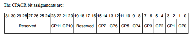
where, CP10 and CP11 are used to control floating point availability. Both fields are 2 bits
and must be identical to correctly configure the FPU.
| bit 1 | bit 0 | CP10 & CP11 FPU Configuration |
|---|---|---|
| 0 | 0 | FPU Disabled (default). Any access generates a UsageFault. |
| 0 | 1 | Privileged access only. Any unprivileged access generates a UsageFault. |
| 1 | 0 | Reserved |
| 1 | 1 | Privileged and unprivileged access allowed. |
Special Registers
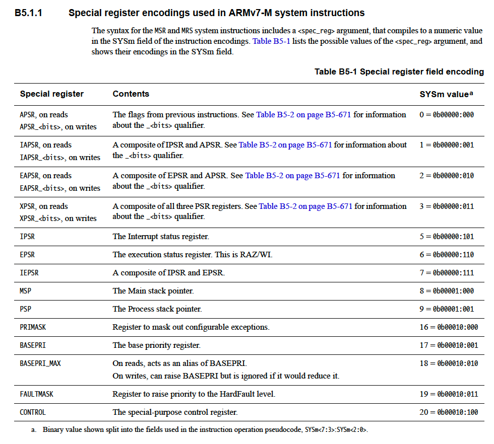
There’s a number of Special Registers which can be written to and read from using the Move to Special Register (MSR) and Move to Register from Special Register (MRS) instructions, respectively.
A full discussion of all the registers is outside the scope of this article but the ARM Reference Manual documentation about the instruction itself has a great overview 2:
There are some special rules about the privilege level needed to read and write to the special registers worth remembering:
Excerpt from “B5.2.2 MRS”2:
If unprivileged code attempts to read any stack pointer, the priority masks, or the IPSR, the read returns zero.
Excerpt from “B5.2.3 MSR”2:
The processor ignores writes from unprivileged Thread mode to any stack pointer, the EPSR, the IPSR, the masks, or CONTROL. If privileged Thread mode software writes a 1 to the CONTROL.nPRIV bit, the processor switches to unprivileged Thread mode execution, and ignores any further writes to special-purpose registers. After any Thread mode transition from privileged to unprivileged execution, software must issue an ISB instruction to ensure instruction fetch correctness.
For context switching, one of the most important special registers is the CONTROL
register. Bits in the register read-as-zero unless they are implemented. The
ARMv8-M architecture3 has the largest number of optional extensions so the most complete assignment
set one will see is:
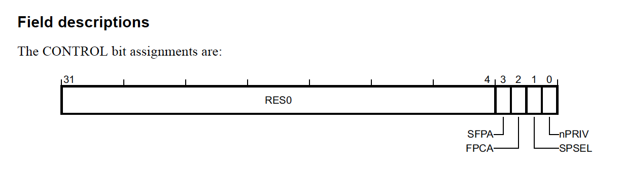
where
-
SFPAindicates whether secure floating-point is active or inactive based on whether the bit is set or not. This is only present when the ARMv8-M Security Extension is implemented -
FPCAindicates whether the floating point context is active. We’ll go into detail below. -
SPSELcontrols what stack pointer is in use. We’ll go into more detail below. -
nPrivcontrols whether or not thread mode is operating as privileged or unprivileged. When set to 1, thread mode operates as unprivileged otherwise it operates as privileged
Stack Pointers
The Cortex-M architecture implements two stacks known as the Main Stack (tracked in the msp register) and the
Process Stack (tracked in the psp register). On reset, the MSP is always active and its initial value is derived
from the first word in the vector table. When a stack pointer is “active”, its current value will
be returned when the sp register is accessed.
In Handler Mode, the msp is always the stack which is used. In Thread Mode, the stack
pointer which is used can be controlled in two ways:
- Writes of 1 to the
SPSELbit in theCONTROLregister will switch from using themspto thepsp - The value placed in
EXC_RETURNupon exception return. We will expand on this below.
Context State Stacking
In our guide about ARM Cortex-M Exception Handling, we touched upon how the hardware itself implements the AAPCS1 so that interrupts can be implemented as normal C functions. Here we will expand on what that actually means.
Per the AAPCS1, there is a certain set of registers that a function is responsible for restoring to their original value before returning to the function which called it:
A subroutine must preserve the contents of the registers r4-r8, r10, r11 and SP (and r9 in PCS variants that designate r9 as v6).
Conversely, this means it is the responsibility of the calling function to preserve the registers not
mentioned, r0 - r3, r12 and LR (r14).
The specification also states the “The [C]PSR is a global register” where “the N, Z, C, V and Q bits (bits 27-31) and the GE[3:0] bits (bits 16-19) are undefined on entry to or return from a public interface.” These bits convey state about recent comparisons, etc. This means it’s also the calling functions responsibility to preserve any state it needs in the register.
The AAPCS also imposes a requirement that “The stack must be double-word aligned.” for “public interfaces” which means when entering a function the stack should always start off 8-byte aligned.
Taking all of these factors into account, in order for execution from an interrupt to be ABI compliant, the ARM architecture needs to align the stack and save the register state that a calling function is responsible for preserving. To accomplish this, the ARM Cortex-M core will push that context onto the stack.
NOTE: The stack data is pushed on is the one which was in use prior to servicing the exception. So for example, if the system was in Thread Mode using the
pspand exception takes place, the data will be pushed on thepsp. If the core was already servicing another exception and was preempted by a higher priority exception, the data will be pushed on themsp.
The reference manual has a great picture of what the stack looks like after this automatic context state saving takes place:
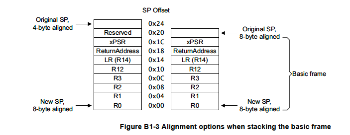
NOTE: On exception entry, the ARM hardware uses bit 9 of the stacked xPSR value to indicate whether 4 bytes of padding was added to align the stack on an 8 byte boundary.
FP Extension & Context State Stacking
When the FP Extension is in use and active, the AAPCS1 states that s16 - s31 must be preserved across
subroutine calls and s0 - s15 do not need to be preserved. Additionally, similar to the PSR
register, the state of the FPU needs to be preserved so the FPSCR needs to be stored as well. This means an additional 17
registers (68 bytes) need to be stacked on exception entry!
Fortunately, the folks at ARM realized this could be a performance or memory problem for some use cases so there are several really neat ways to optimize this.
As we mentioned above, one option is to completely disable the FPU. In this situation no state needs to be preserved.
However, there’s also some fine granularity controls about how the context is preserved. These can
be configured via the Floating Point Context Control Register (FPCCR) located at address
0xE000EF34:
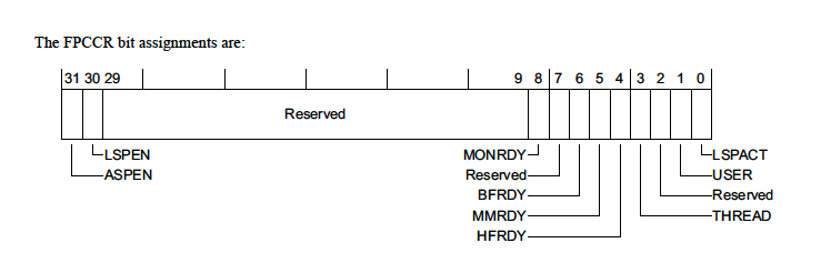
With respect to Context State Stacking, the values that are interesting are:
-
ASPEN- When set to1(default), any execution of a floating point instruction will set theFPCAbit in the control register we mentioned above. -
LSPEN- When set to1(default) enables what is known as a lazy context save4. Basically what this means is on exception entry, space will be reserved on the stack for the caller saved floating point registers (s0-s15&FPSCR) but the data will not actually be pushed by default. If and only if a floating point instruction is executed while in the exception, only then will the state be pushed. This is pretty sweet because it means as long as an interrupt does not use the FPU, no extra interrupt latency penalty is incurred!
When the FPU is “in use” (CONTROL.FPCA=1), an extended frame will be saved by the hardware:
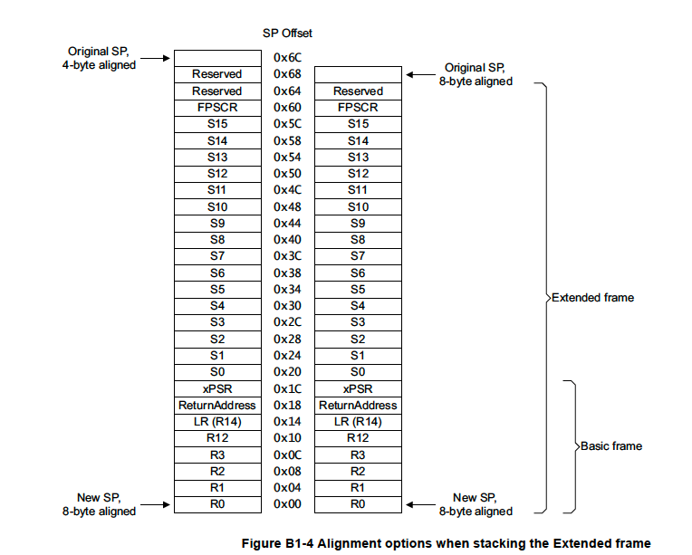
NOTE: If the FPU is enabled but no floating point instructions are executed or ASPEN is disabled (i.e CONTROL.FPCA=0), only the basic frame will be saved. The ARM lazy context save application note4 explores some interesting tricks one can play based on these facts to prevent the extended frame from always needing to be allocated even when the FPU is in use.
Exception Return
Finally, in order for the hardware to figure out what state to restore when exiting an
exception, a special value, known as EXC_RETURN needs to be loaded into the link register, lr. Typically, this
will just mirror the value in the lr on exception entry. However, a different value can also be
manually loaded into the register as well (i.e to change the Thread Mode stack pointer
being used like we discussed above).
On exception entry, the ARM reference manual pseudocode for the value stored in lr gives the best description5:
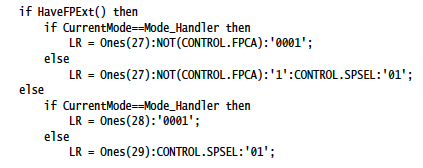
It describes the current stack frame in use (Extended vs Basic) as well as what the active stack pointer was prior to the exception taking place.
When returning from an exception, the possible values and behavior for EXC_RETURN are:
| EXC_RETURN Value | Mode to Return To | Stack to use |
|---|---|---|
| 0xFFFFFFF1 | Handler Mode | MSP |
| 0xFFFFFFF9 | Thread Mode | MSP |
| 0xFFFFFFFD | Thread Mode | PSP |
| 0xFFFFFFE1 | Handler Mode (FPU Extended Frame) | MSP |
| 0xFFFFFFE9 | Thread Mode (FPU Extended Frame) | MSP |
| 0xFFFFFFED | Thread Mode (FPU Extended Frame) | PSP |
RTOS Context Switching
An RTOS at its cores offers several basic primitives:
- A scheduler capable of context switching between different tasks. Tasks can usually be prioritized and at a bare minimum a scheduler is usually capable of alternating between tasks when new events arrive (i.e a new accelerometer sample is available) or when the task yields its slot.
- Very basic Operating System primitives (such as mutexes/semaphores and a way to pass messages between tasks)
- Configuration operations for sandboxing different code from one another by leveraging the privilege and access control features the hardware offers.
Schedulers usually come in two main varieties:
- Preemptive - A context switch while a task is “running” if something more important comes up.
- Cooperative - A context switch will never occur while another task is “running”. A task must explicitly yield for another task to run. Tasks must “co-operate” for everyone to get a chance to run.
When an RTOS scheduler decides a different task should be run than what is currently running, it will trigger a context switch. When switching from one task to another, the “state” of the current task needs to be preserved in some way. This includes information such as the execution state of the task (i.e blocked on a mutex, sleeping, etc) and the values of the active hardware registers.
As we alluded to in our
ARM Cortex-M Exception
article, the SVCall, PendSV, and SysTick interrupts integrated into every Cortex-M device
were explicitly designed to make task management simple. Consequently, the context switching logic
winds up looking extremely similar regardless of the RTOS in use. So if you understand how one
works, you will be able to pretty easily learn how any other one works!
In the sections that follow we will walk through step-by-step how the context switcher within FreeRTOS6 works for Cortex-M devices. FreeRTOS is a very popular (and open source!) RTOS found in numerous commercial products. It has a great track record and has been around since ~2003 by Real Time Engineers Ltd. In 2017 the company was acquired by Amazon, who now manages the project.
Demystifying the FreeRTOS Context Switcher
For this setup we will use:
- a nRF52840-DK7 (ARM Cortex-M4F) as our development board
- SEGGER JLinkGDBServer8 as our GDB Server.
- GCC 8.3.1 / GNU Arm Embedded Toolchain as our compiler9
- GNU make as our build system
All the code can be found on the
Interrupt Github page with more
details in the README in the directory linked.
The example application itself is very basic: it creates a “Ping” FreeRTOS task and a “Pong” FreeRTOS task. The “Ping” task sends a message to the “Pong” task once per second and each time the event loop in a task runs, I’ve added a breakpoint instruction so we can confirm with the debugger the tasks are switching between each other.
The Port
FreeRTOS has excellent documentation10 about creating a new project. If you are trying to port FreeRTOS to your own platform, I’d strongly recommend reading through those docs. For context, the approximate steps I followed for the minimal port to the Cortex-M4 are:
- Set up a build system and startup sequence for your MCU. Extensive details about what these steps look like can be found in our zero to main() series.
- Compile the core source files included in the FreeRTOS Kernel11 (
tasks.c,queue.c,list.c,timers.c) - Choose a “port”. A port is the platform specific files needed for the architecture in use. Since
ports often wind up having assembly and assembly syntax is compiler specific there will often be
ports per compiler for a given architecture. The FreeRTOS Kernel 11 already has a default
port for pretty much any architecture imaginable so usually you can just choose one from there. In our
case, we want a port for a Cortex-M4F which can be found in
portable/GCC/ARM_CM4F/. Once you find the “port” you will need to addport.cto your compilation list. - Chose a FreeRTOS heap implementation12. I went with the most basic one for the example,
portable/MemMang/heap_1.c - Add the port directory (in our case
portable/GCC) and the root directory of the kernel as include paths to the build system. - Create a
FreeRTOSConfig.h13 with the configuration settings for your particular application - Create some tasks (
xTaskCreate), start the scheduler (vTaskStartScheduler), and you are ready to go!
Compiling the code and launching it with GDB
# Compile the code
$ make
Compiling main.c
Compiling startup.c
Compiling freertos_kernel/tasks.c
Compiling freertos_kernel/queue.c
Compiling freertos_kernel/list.c
Compiling freertos_kernel/timers.c
Compiling freertos_kernel/portable/GCC/ARM_CM4F/port.c
Compiling freertos_kernel/portable/MemMang/heap_1.c
Linking library
Generated build/nrf52.elf

# In one terminal, start a GDB Server
$ JLinkGDBServer  -if swd -device nRF52840_xxAA
SEGGER J-Link GDB Server V6.52a Command Line Version

# Flash the code on the NRF52 and start gdb
$ arm-none-eabi-gdb-py --eval-command="target remote localhost:2331" --ex="mon reset" --ex="load"
--ex="mon reset" --se=build/nrf52.elf
GNU gdb (GNU Tools for Arm Embedded Processors 8-2019-q3-update) 8.3.0.20190703-git
Copyright (C) 2019 Free Software Foundation, Inc.
[...]
Resetting target
Loading section .interrupts, size 0x40 lma 0x0
Loading section .text, size 0x194d lma 0x40
Loading section .data, size 0x4 lma 0x1990
Start address 0x40, load size 6545
Transfer rate: 2130 KB/sec, 2181 bytes/write.
Resetting target
(gdb)
Context Switching
Let’s start by looking at the code that deals with context switching itself. Once we understand that, we will cycle back to how the scheduler itself is started and tasks are created.
The FreeRTOS scheduler works by utilizing the built in SysTick and PendSV interrupts. The
SysTick is configured to fire periodically. Each time it fires, a check is performed to see if a
context switch is required by calling xTaskIncrementTick:
void xPortSysTickHandler( void )
{
    /* The SysTick runs at the lowest interrupt priority, so when this interrupt
    executes all interrupts must be unmasked.  There is therefore no need to
    save and then restore the interrupt mask value as its value is already
    known. */
    portDISABLE_INTERRUPTS();
    {
        /* Increment the RTOS tick. */
        if( xTaskIncrementTick() != pdFALSE )
        {
            /* A context switch is required.  Context switching is performed in
            the PendSV interrupt.  Pend the PendSV interrupt. */
            portNVIC_INT_CTRL_REG = portNVIC_PENDSVSET_BIT;
        }
    }
    portENABLE_INTERRUPTS();
}
A context switch may also occur outside of this if a task decides to yield (portYIELD).
Both of these paths trigger the PendSV exception, where the real magic happens:
// FreeRTOSConfig.h

#define vPortSVCHandler    SVC_Handler
#define xPortPendSVHandler PendSV_Handler
#define xPortSysTickHandler SysTick_Handler

// port.c
void xPortPendSVHandler( void )
{
    /* This is a naked function. */

    __asm volatile
        (
        "       mrs r0, psp                     \n"
        "       isb                             \n"
        "                                       \n"
        "       ldr     r3, pxCurrentTCBConst   \n" /* Get the location of the current TCB. */
        "       ldr     r2, [r3]                \n"
        "                                       \n"
        "       tst r14, #0x10                  \n" /* Is the task using the FPU context?  If so, push high vfp registers. */
        "       it eq                           \n"
        "       vstmdbeq r0!, {s16-s31}         \n"
        "                                       \n"
        "       stmdb r0!, {r4-r11, r14}        \n" /* Save the core registers. */
        "       str r0, [r2]                    \n" /* Save the new top of stack into the first member of the TCB. */
        "                                       \n"
        "       stmdb sp!, {r0, r3}             \n"
        "       mov r0, %0                      \n"
        "       msr basepri, r0                 \n"
        "       dsb                             \n"
        "       isb                             \n"
        "       bl vTaskSwitchContext           \n"
        "       mov r0, #0                      \n"
        "       msr basepri, r0                 \n"
        "       ldmia sp!, {r0, r3}             \n"
        "                                       \n"
        "       ldr r1, [r3]                    \n" /* The first item in pxCurrentTCB is the task top of stack. */
        "       ldr r0, [r1]                    \n"
        "                                       \n"
        "       ldmia r0!, {r4-r11, r14}        \n" /* Pop the core registers. */
        "                                       \n"
        "       tst r14, #0x10                  \n" /* Is the task using the FPU context?  If so, pop the high vfp registers too. */
        "       it eq                           \n"
        "       vldmiaeq r0!, {s16-s31}         \n"
        "                                       \n"
        "       msr psp, r0                     \n"
        "       isb                             \n"
        "                                       \n"
        "                                       \n"
        "       bx r14                          \n"
        "                                       \n"
        "       .align 4                        \n"
        "pxCurrentTCBConst: .word pxCurrentTCB  \n"
        ::"i"(configMAX_SYSCALL_INTERRUPT_PRIORITY)
    );
}
Let’s halt the debugger in this function and step through instruction by instruction discussing what is actually happening.
(gdb) mon reset
Resetting target
(gdb) c
Continuing.

Program received signal SIGTRAP, Trace/breakpoint trap.
prvQueuePingTask (pvParameters=<optimized out>) at main.c:33
33      __asm("bkpt 1");
(gdb) break PendSV_Handler
Breakpoint 2 at 0x1430: file freertos_kernel/portable/GCC/ARM_CM4F/port.c, line 435.
(gdb) n
34      xQueueSend(xQueue, &ulValueToSend, 0U);
(gdb) c
Continuing.

Breakpoint 2, PendSV_Handler () at freertos_kernel/portable/GCC/ARM_CM4F/port.c:435
435		__asm volatile
Great, we are halted on the first line of the context switcher. As we discussed
above, the hardware will automatically save registers on exception
entry for us. We can figure out how things are stacked by looking at the current lr value which
encodes this information.
(gdb) p/x $lr
$7 = 0xfffffffd
Using this info we know that the code was executing in thread mode and using the
psp for it’s stack. We also know that the FPU context was not active.
This tells us a basic frame was saved by the hardware on the
psp. We can walk up the stack using x/a with gdb to dump the register values.
I’ve annotated the registers being read inline below:
(gdb) x/a $psp // top of stack will be $r0
0x200005a0 <ucHeap+1096>:	0x1 <g_pfnVectors+1>
(gdb) <enter to get $r1>
0x200005a4 <ucHeap+1100>:	0x200003b4 <ucHeap+604>
(gdb) <enter to get $r2>
0x200005a8 <ucHeap+1104>:	0x10000000
(gdb) <enter to get $r3>
0x200005ac <ucHeap+1108>:	0x0 <g_pfnVectors>
(gdb) <enter to get $r12 >
0x200005b0 <ucHeap+1112>:	0x200001a8 <ucHeap+80>
(gdb) <enter to get $lr>
0x200005b4 <ucHeap+1116>:	0xbd1 <xQueueGenericSend+152>
(gdb) <enter to get ReturnAddress>
0x200005b8 <ucHeap+1120>:	0x1422 <vPortExitCritical+30>
(gdb) <enter to get xPSR>
// notice bit 9 is not set so there is no padding byte
0x200005bc <ucHeap+1124>:	0x6100f000
Now we are ready to walk through the assembly code that makes up the context switcher. First we have:
        "       mrs r0, psp                     \n"
        "       isb                             \n"
We see that the current location of the psp (the stack that was in use prior to exception entry) is
loaded into r0 using the mrs instruction detailed above. This is followed by
an isb (Instruction Synchronization Barrier) which flushes the instruction pipeline
guaranteeing any instruction which follows will be re-fetched. Technically it doesn’t really serve
any purpose here and shouldn’t be required at all14.
// step over the first two instructions (can also type "si 2" for short)
(gdb) step instruction 2
Moving on we have:
        "       ldr     r3, pxCurrentTCBConst   \n" /* Get the location of the current TCB. */
        "       ldr     r2, [r3]                \n"
[...]
        "pxCurrentTCBConst: .word pxCurrentTCB  \n"
What’s happening here is a label with the location of the C variable, pxCurrentTCB, is loaded into
$r3. Then the value of pxCurrentTCB gets loaded into $r2. We can confirm this by stepping through
the two instructions and comparing the registers with the C types.
(gdb) step instruction
(gdb) p/x $r3
$23 = 0x20000008
(gdb) p &pxCurrentTCB
$24 = (TCB_t * volatile *) 0x20000008 <pxCurrentTCB>
(gdb) step instruction
(gdb) p/x $r2
$25 = 0x20000610
(gdb) p pxCurrentTCB
$26 = (TCB_t * volatile) 0x20000610 <ucHeap+1208>
Next we have:
        "       tst r14, #0x10                  \n" /* Is the task using the FPU context?  If so, push high vfp registers. */
        "       it eq                           \n"
        "       vstmdbeq r0!, {s16-s31}         \n"
This set of instructions checks to see if the FPU Context was active prior to exception
entry. This can be resolved by reading the information passed via the $lr register on exception
entry (more details above). If bit 5 is 0, the FPU is active,
otherwise it is not. The tst (Test) instruction performs a logical AND operation between the
register and the immediate value provided (so in this case r14 & 0x10). It then populates
condition flags in the PSR register based on the result. Condition flags available include a “Zero
condition flag” which means the result of the AND was zero.
The it (If-Then) instruction is then used to conditionally execute further
instructions based on the current state in the condition flags. it eq is shorthand for “if the
result of the last comparison was zero then execute the instruction that follows”. The following
instruction pushes the callee-saved floating point registers onto the psp (currently stored in r0). In our
case the result is not zero so this instruction should be skipped. We should see the psp
remains unchanged from the value we originally dumped:
(gdb) p/x $r0
$1 = 0x200005a0
(gdb) si 4
(gdb) x/i $pc
=> 0x1446 <PendSV_Handler+22>:	stmdb	r0!, {r4, r5, r6, r7, r8, r9, r10, r11, lr}
(gdb) p/x $r0
$1 = 0x200005a0
WARNING: Over the years I’ve seen a lot of nasty stack overflows arise here which can be tricky to track down. As soon as an FPU instruction is used an additional 132 bytes will be pushed on the stack, which can lead to unexpected overflows of small embedded stacks
This brings us to the next part which is pretty self explanatory:
        "       stmdb r0!, {r4-r11, r14}        \n" /* Save the core registers. */
        "       str r0, [r2]                    \n" /* Save the new top of stack into the first member of the TCB. */
We push all the callee-saved core
registers onto psp using the stmdb (Store Multiple Decrement Before stores multiple
registers) instruction and then update the first word in our pxCurrentTCB pointer with the
updated stack location (stored in r0).
pxCurrentTCB is a FreeRTOS symbol that is always
populated with the running task. A TCB (Task Control Block) contains various state associated
with the task. Looking at the source code we see the first word is:
typedef struct tskTaskControlBlock /_ The old naming convention is used to prevent breaking kernel aware debuggers. _/
{
volatile StackType_t _pxTopOfStack; /_< Points to the location of the last item placed on
the tasks stack. THIS MUST BE THE FIRST MEMBER OF THE TCB STRUCT. \*/
[...]
We can also look confirm this is what is happening by comparing the C types with register values
within gdb:
(gdb) si
0x0000144a	435		__asm volatile
(gdb) p/x $r0
$2 = 0x2000057c
(gdb) x/i $pc
=> 0x144a <PendSV_Handler+26>:	str	r0, [r2, #0]
(gdb) p/x pxCurrentTCB->pxTopOfStack
$3 = 0x200005a4
(gdb) si
0x0000144c	435		__asm volatile
(gdb) p/x pxCurrentTCB->pxTopOfStack
$4 = 0x2000057c
Awesome! At this point we have saved all the register state of the original task and recorded that location within the task specific TCB context. Now it’s time to actually context switch over to a new task:
        "       stmdb sp!, {r0, r3}             \n"
        "       mov r0, %0                      \n"
        "       msr basepri, r0                 \n"
        "       dsb                             \n"
        "       isb                             \n"
        "       bl vTaskSwitchContext           \n"
[...]
        ::"i"(configMAX_SYSCALL_INTERRUPT_PRIORITY)
We see the port uses a GCC feature known as Extended Asm15 to mix C macros with ARM
assembly. This block prepares to call the context switch logic, vTaskSwitchContext, a C function which
determines the next task to run. First the “argument” registers are saved on the active stack
(always msp for exceptions). Next interrupts below configMAX_SYSCALL_INTERRUPT_PRIORITY
are disabled since it is only safe to access the data structures accessed by vTaskSwitchContext
without interruption. If interrupts were not disabled, the context switching code could be
preempted and a call to a FreeRTOS *_FromISR() API could corrupt the data structure.
When lowering the effective execution level, an isb instruction is required for the new priority to be visible for future
instructions. The dsb instruction shouldn’t be explicitly necessary here16. Finally we call
the C function. From FreeRTOS documentation we can conclude what will happen:
/*
 * THIS FUNCTION MUST NOT BE USED FROM APPLICATION CODE.  IT IS ONLY
 * INTENDED FOR USE WHEN IMPLEMENTING A PORT OF THE SCHEDULER AND IS
 * AN INTERFACE WHICH IS FOR THE EXCLUSIVE USE OF THE SCHEDULER.
 *
 * Sets the pointer to the current TCB to the TCB of the highest priority task
 * that is ready to run.
 */
 portDONT_DISCARD void vTaskSwitchContext( void ) PRIVILEGED_FUNCTION;
So when the function returns pxCurrentTCB should be populated with the new task to switch to.
Let’s try it out!
// display the name
(gdb) p pxCurrentTCB->pcTaskName
$6 = "Ping", '\000' <repeats 11 times>
(gdb) si 5
0x00001460	435		__asm volatile
(gdb) x/i $pc
=> 0x1460 <PendSV_Handler+48>:	bl	0x760 <vTaskSwitchContext>
// step over the function call using "next instruction" ("ni")
(gdb) ni
0x00001464	435		__asm volatile
(gdb) x/i $pc
=> 0x1464 <PendSV_Handler+52>:	mov.w	r0, #0
(gdb) p pxCurrentTCB->pcTaskName
$7 = "Pong", '\000' <repeats 11 times>
We see that the pxCurrentTCB has changed from the “Ping” task to the “Pong” task.
Upon return from the function call, all interrupts are re-enabled by resetting basepri to 0 and the initial values of
the argument registers ($r0-$r3) prior to the function invocation are restored by popping them
off the stack. No synchronization instructions are required for the msr call because the
ARM core will actually take care of this for you when the execution priority increases 17. Let’s
step over this block:
        "       mov r0, #0                      \n"
        "       msr basepri, r0                 \n"
        "       ldmia sp!, {r0, r3}             \n"
(gdb) si 3
0x0000146e in PendSV_Handler () at freertos_kernel/portable/GCC/ARM_CM4F/port.c:435
435		__asm volatile
(gdb) x/i $pc
=> 0x146e <PendSV_Handler+62>:	ldr	r1, [r3, #0]
Now it’s time to actually start up the new task. Recall when we saved the “Ping” task state above, we placed the
location of the task stack in pxTopOfStack. So to recover the task state of the “Pong” task we
just need to do the opposite. First this requires loading up the new TCB_t that pxCurrentTCB points to:
        "       ldr r1, [r3]                    \n" /* The first item in pxCurrentTCB is the task top of stack. */
        "       ldr r0, [r1]                    \n"
(gdb) p/x pxCurrentTCB
$8 = 0x200003b0
(gdb) si
0x00001470	435		__asm volatile
(gdb) p/x $r1
$11 = 0x200003b0
(gdb) p/x pxCurrentTCB->pxTopOfStack
$12 = 0x20000324
(gdb) si
0x00001472	435		__asm volatile
(gdb) p/x $r0
$13 = 0x20000324
r0 now holds a pointer to the top of the stack for the task we want to switch to. First we pop
the callee-saved core registers using the ldmia (Load Multiple Increment After) instruction,
then we check the restored value in the $lr / $r14 register to determine if there is any FPU
state which needs to be restored as well (in our case, it does not):
        "       ldmia r0!, {r4-r11, r14}        \n" /* Pop the core registers. */
        "                                       \n"
        "       tst r14, #0x10                  \n" /* Is the task using the FPU context?  If so, pop the high vfp registers too. */
        "       it eq                           \n"
        "       vldmiaeq r0!, {s16-s31}         \n"
        "                                       \n"
(gdb) si 4
0x00001480	435		__asm volatile
(gdb) x/i $pc
=> 0x1480 <PendSV_Handler+80>:	msr	PSP, r0
Now r0 points to the location of the program stack exactly as it was when the “Pong” task originally got context
switched out via the PendSV exception handler! Let’s take a look at the stack just like we did on
exception entry:
(gdb) x/a $r0 // contains $r0 value for "Pong" task
0x20000348 <ucHeap+496>:	0x0 <g_pfnVectors>
(gdb) < enter for $r1 >
0x2000034c <ucHeap+500>:	0x200003b4 <ucHeap+604>
(gdb) < enter for $r2 >
0x20000350 <ucHeap+504>:	0x20000000 <uxCriticalNesting>
(gdb) < enter for $r3 >
0x20000354 <ucHeap+508>:	0x10000000
(gdb) < enter for $r12 >
0x20000358 <ucHeap+512>:	0x0 <g_pfnVectors>
(gdb) < enter for $r14 / $lr >
0x2000035c <ucHeap+516>:	0x5d9 <xTaskResumeAll+40>
(gdb) < enter for ReturnAddress - the pc that should be fetched upon return >
0x20000360 <ucHeap+520>:	0xe2a <xQueueReceive+246>
(gdb) < psr value>
0x20000364 <ucHeap+524>:	0x61000000
The last thing we need to do is change the location of the psp to match the value in r0
and populate the link register (r14) with the special EXC_RETURN value we
just recovered from the “Pong” task stack with the ldmia instruction. This will tell the hardware
how return to Thread Mode and restore the context state that was automatically saved correctly:
        "       msr psp, r0                     \n"
        "       isb                             \n"
        "                                       \n"
        "                                       \n"
        "       bx r14                          \n"
        "                                       \n"
Based on the dump of the top of the “Pong” stack we did above, we expect to see $sp=0x20000368,
$pc=0xe2a, $lr=0x5d9 after the branch to r14. Let’s give it a try:
// state prior to branching
(gdb) info reg
[...]
sp             0x20002a88          0x20002a88
lr             0xfffffffd          4294967293
pc             0x1480              0x1480 <PendSV_Handler+80>
xpsr           0x2100000e          553648142
msp            0x20002a88          536881800
psp            0x200005a0          536872352
[...]
(gdb) si 3
// state after branching
xQueueReceive (xQueue=0x20000160 <ucHeap+8>, pvBuffer=pvBuffer@entry=0x2000039c <ucHeap+580>, xTicksToWait=<optimized out>, xTicksToWait@entry=4294967295) at freertos_kernel/queue.c:1378
1378						portYIELD_WITHIN_API();
(gdb) info reg
sp             0x20000368          0x20000368 <ucHeap+528>
lr             0x5d9               1497
pc             0xe2a               0xe2a <xQueueReceive+246>
xpsr           0x61000000          1627389952
msp            0x20002a88          536881800
psp            0x20000368          536871784
(gdb) bt
#0  xQueueReceive (xQueue=0x20000160 <ucHeap+8>, pvBuffer=pvBuffer@entry=0x2000039c <ucHeap+580>, xTicksToWait=<optimized out>, xTicksToWait@entry=4294967295) at freertos_kernel/queue.c:1378
#1  0x00000084 in prvQueuePongTask (pvParameters=<optimized out>) at main.c:41
#2  0x00001334 in ?? () at freertos_kernel/portable/GCC/ARM_CM4F/port.c:703
They values match! We’ve successfully completed a context switch and are running the pong task!
Starting the FreeRTOS Scheduler
The astute observer reader may wonder how the scheduler starts in the first place. What happens if a PendSV gets triggered but there isn’t a currently running task because the system just booted?!
There are several different strategies but a common pattern an RTOS will follow when creating a new task is
to initialize the task stack to look like it had been context switched out by the scheduler. Then
to start the scheduler itself by triggering a SVC exception with the svc instruction. This way
starting a thread is nearly identical to context switching to a thread.
During initialization you will also usually find a couple extra configuration settings such as:
- Configuration as to whether or not tasks operate at privileged or unprivileged level
- FP Extension configuration (i.e whether or not the FPU is enabled and what context stacking schema to use). For example, the port used in the example does the following FPU configuration:
static void vPortEnableVFP( void )
{
    __asm volatile
    (
        "	ldr.w r0, =0xE000ED88		\n" /* The FPU enable bits are in the CPACR. */
        "	ldr r1, [r0]				\n"
        "								\n"
        "	orr r1, r1, #( 0xf << 20 )	\n" /* Enable CP10 and CP11 coprocessors, then save back. */
        "	str r1, [r0]				\n"
        "	bx r14						"
    );
}
[...]
BaseType_t xPortStartScheduler( void )
{
[...]
    /* Ensure the VFP is enabled - it should be anyway. */
    vPortEnableVFP();

    /* Lazy save always. */
    *( portFPCCR ) |= portASPEN_AND_LSPEN_BITS;
[...]
To start FreeRTOS and get tasks to runvTaskStartScheduler needs to be called. If you are
interested in taking a closer look at this logic, I’d recommend looking at are pxPortInitialiseStack,
xPortStartScheduler, and vPortSVCHandler functions in port.c.
Closing
We hope you learned something interesting about how the ARM Cortex-M architecture hardware helps to enable multi-tasking and developed a better understanding of how the FreeRTOS implementation works.
We’d love to hear interesting RTOS bugs you have tracked down or other topics you would like to see covered on the topic. Let me know in the discussion area below!
Interested in learning more about debugging HardFaults? Watch this webinar recording..
See anything you'd like to change? Submit a pull request or open an issue on our GitHub
Reference Links
 Chris Coleman is a founder and CTO at Memfault. Prior to founding Memfault, Chris worked on the embedded software teams at Sun, Pebble, and Fitbit.